RadRover 6 Plus and RadCity 5 Plus Wiring Harness Replacement Guide
The wiring harness connects various electrical components on the bike and can be replaced in the unlikely event it is damaged or determined to be non-functional by Rad Power Bikes Product Support.
The wiring harness replacement involves unplugging the connectors, removing the harness from the downtube and replacing it with a new one, and plugging in the connectors.
Watch the following video, or use the steps below to replace the wiring harness.
Overview
The process will require you to unplug connectors and loosen (or remove) bolts, so you can uninstall the wiring harness (with its jumper cable, if you have one). You will then need to install the new wiring harness (and jumper cable, if your new harness came with one), which will require you to carefully plug the connectors into the new wiring harness and reinstall the bolts that hold the external cable protector.
You will need:
- Flat side cutters
- A 2.5 mm Allen wrench (RadRover 6 Plus)
- A 3 mm Allen wrench (RadCity 5 Plus)
- A few replacement zip ties
- A friend to help hold the bike in place
- And the replacement wiring harness from Rad Power Bikes
Hardware may vary (bolt head style) and/or require different tools. Use the appropriate head size and type of tool for your bolts. Ensure the tool is pressed firmly into the bolt head and turn slowly to prevent stripping.
Before you start
Before checking the connectors, determine whether your bike has a jumper cable. The jumper cable will be preinstalled on some models.
The jumper cable is an extra piece of cable that some bikes have incorporated into the wiring harness as shown in the second illustration below. Whether or not you have a jumper cable will affect which connector check steps apply to you.
- If your accessory cable doesn't connect with anything (it has a connector cover on its end), you do not have a jumper cable.
- If the accessory cable loops back up toward your wiring harness and connects to another cable, you do have a jumper cable.
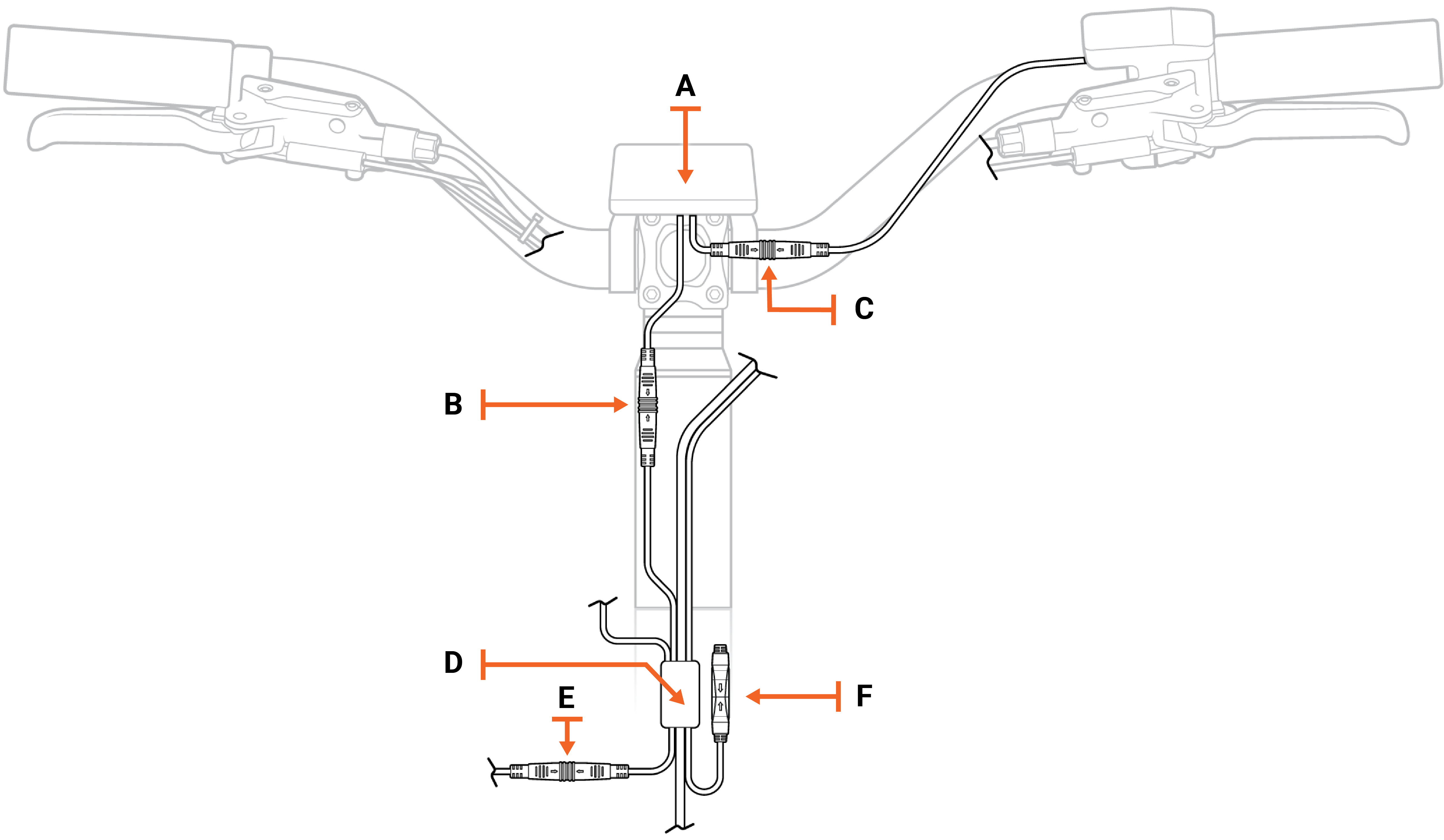
Above: Wiring harness without a jumper cable
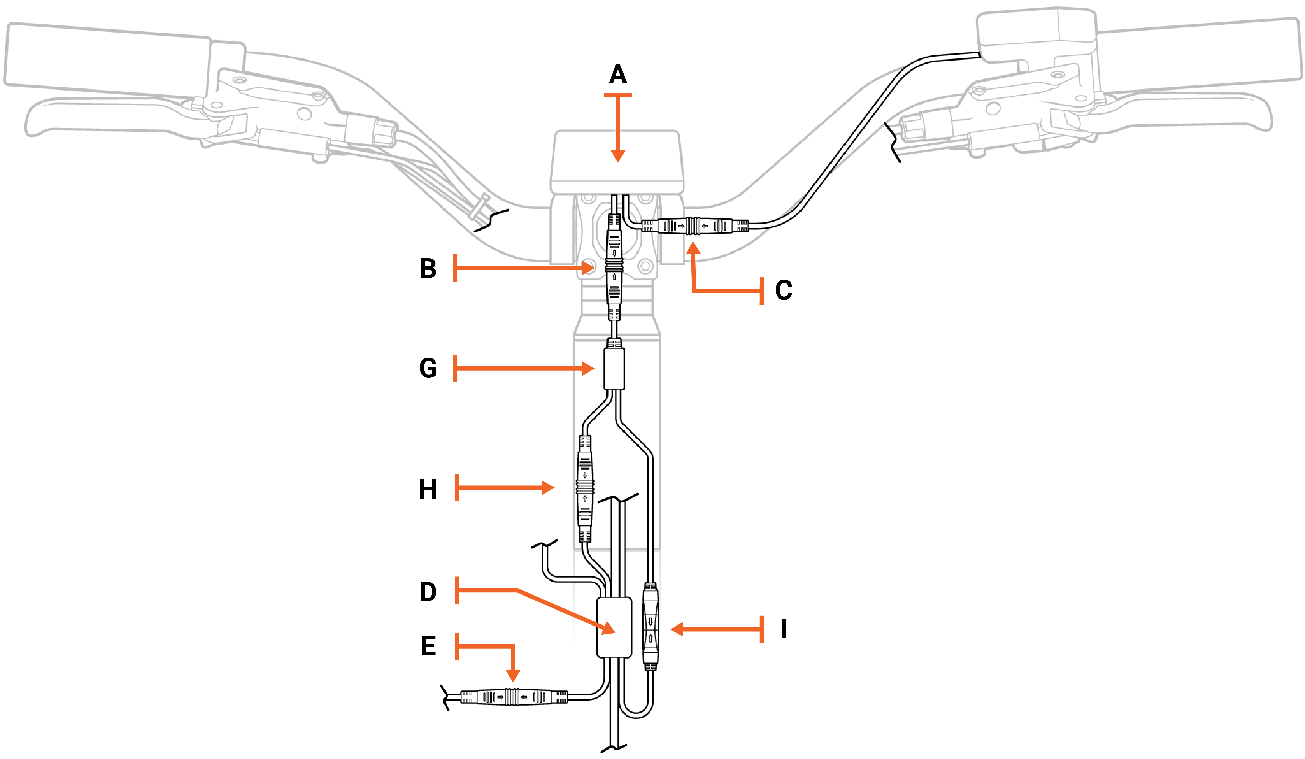
Legend (for wiring harness illustrations above and below)
| A | Rad UI Display |
| B | Rad UI Display connector to the wiring harness (on bikes without a jumper cable). On bikes with a jumper cable, this connector connects to the jumper cable. |
| C | Rad UI Display connector to the Rad UI Remote |
| D | Wiring harness junction |
| E | Wiring harness to headlight connector |
| F | Accessory port with connector cover on its end |
| G | Jumper cable junction |
| H | Jumper cable connected to the wiring harness |
| I | Jumper cable connected to the accessory port |
Below: Wiring harness with a jumper cable
Remove the old wiring harness
Get the bike ready for maintenance. Turn off the bike, remove the battery, and press the power button to discharge remaining power.
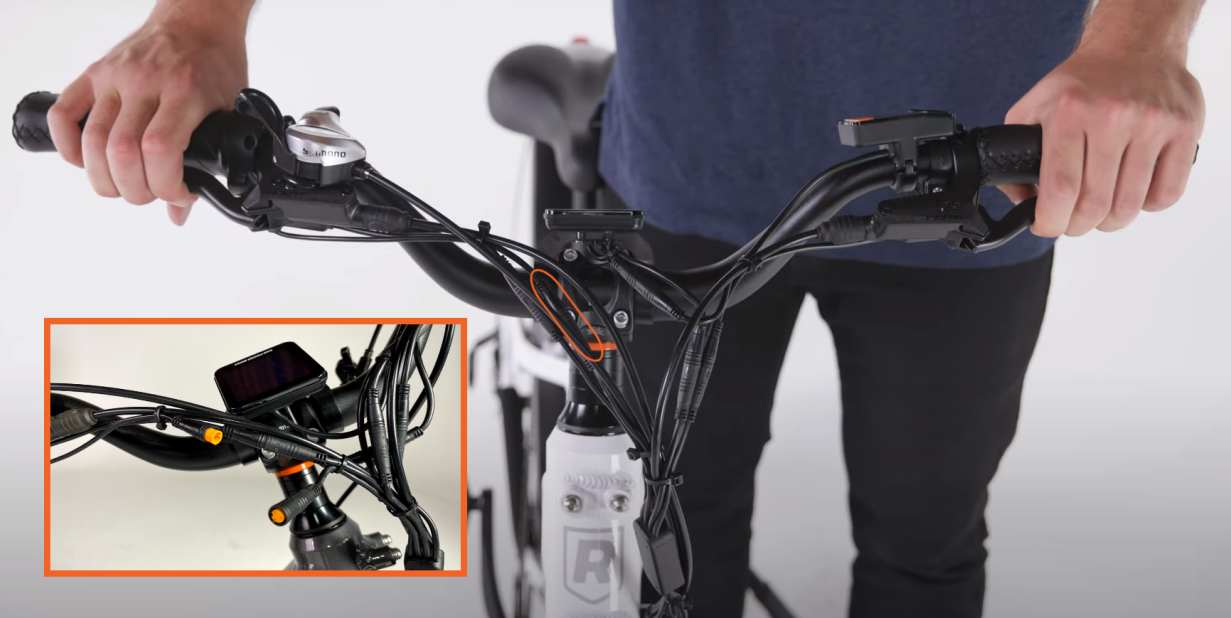
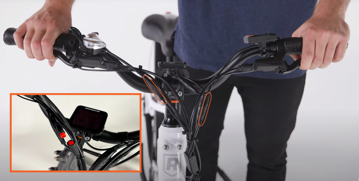
Locate the wiring harness connectors at the front of the bike and snip the zip ties securing the bundle of cables.
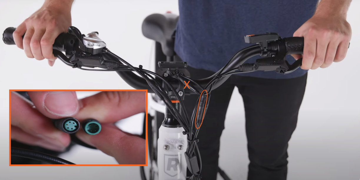
Unplug the wiring harness and jumper cable connectors near the handlebars. Locate each connector at the front of the bike, and pull the connector ends apart without twisting. Snip zip ties as needed for slack.
- Locate and disconnect the Rad UI Display connector that goes to the jumper cable. There are two cables that connect to the Rad UI Display. You want the one that connects to the jumper cable and NOT to the Rad UI Remote. The interior of the Rad UI Display connector is green.
- Locate and disconnect the throttle connector. Trace the cable from the throttle on the handlebar to the connector at the front of the bike. Its interior will be orange.
- Locate and disconnect the left and right brake connectors. Find each of the brake connectors by tracing the cable from each brake lever on the handlebar to the connector. Its interior will be red.
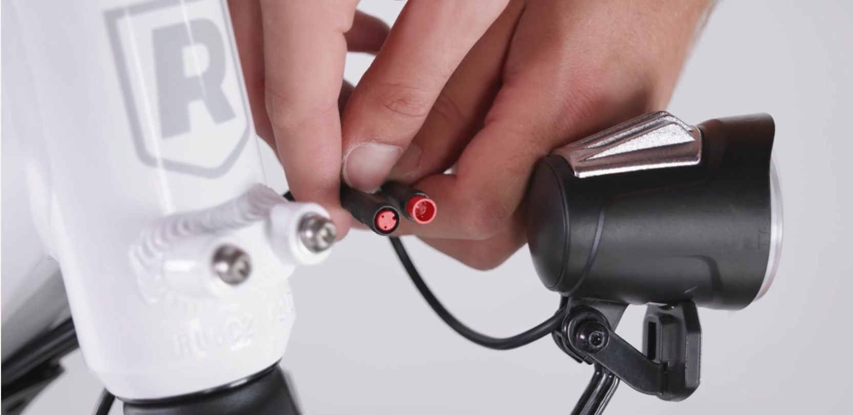
- Locate and disconnect the headlight connector. Trace the cable from the headlight to find your headlight connector. Its interior is red.
Note: If you have any accessories attached to the accessory port, such as a USB charger, unplug the accessory by pulling the accessory from the accessory port (black interior) and jumper cable (black interior) connections apart, without twisting, and set the accessory aside. Review the accessory’s installation guide to reinstall it after installing the new wiring harness (and jumper cable).
Unplug the wiring harness connectors near the handlebars. Locate each connector at the front of the bike, and pull the connector ends apart without twisting. Snip zip ties as needed for slack.
- Locate and disconnect the Rad UI Display connector that goes to the wiring harness. There are two cables that connect to the Rad UI Display. You want the one that connects to the wiring harness and NOT to the Rad UI Remote.
- Locate and disconnect the throttle connector. Trace the cable from the throttle on the handlebar to the connector at the front of the bike. Its interior will be orange.
- Locate and disconnect the left and right brake connectors. Find each of the brake connectors by tracing the cable from each brake lever on the handlebar to the connector. Its interior will be red.
- Locate and disconnect the headlight connector. Trace the cable from the headlight to find your headlight connector. Its interior is red.
Note: If you have any accessories attached to your accessory port, such as a USB charger, unplug the accessory by pulling the accessory port (black interior) connection apart, without twisting, and set the accessory aside. Review the accessory’s installation guide to reinstall it after installing the new wiring harness.
Loosen the external cable cover. Using a 2.5 mm Allen wrench, partially unscrew the four bolts connecting the external cable protector to the frame. Pull the wiring harness cable from underneath the external cable protector so that it hangs freely.
.png?revision=1)
Locate and unplug the remaining connectors. Snip any nearby zip ties if you need cable slack, and pull each side of the connector apart, without twisting, to unplug.
- Locate and disconnect the wiring harness connector by tracing the wiring harness down the downtube. Its interior will be black with 11 pins.
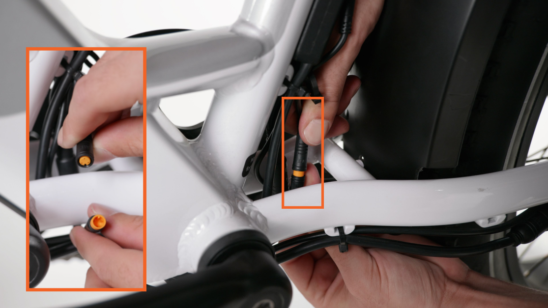
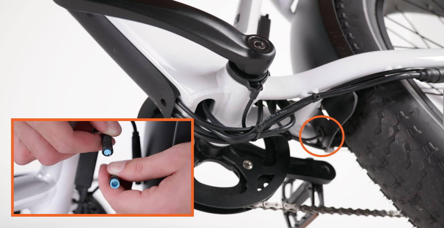
- Locate and disconnect the pedal-assist sensor (PAS) connector. Trace the cable coming out of the left crank arm (the side without the chain). Its interior is orange.
- Locate and disconnect the motor connector. Trace the cable coming out of the motor, at the chainstay on the bike’s left side (the side without the chain). Its interior is black with 3 pins.
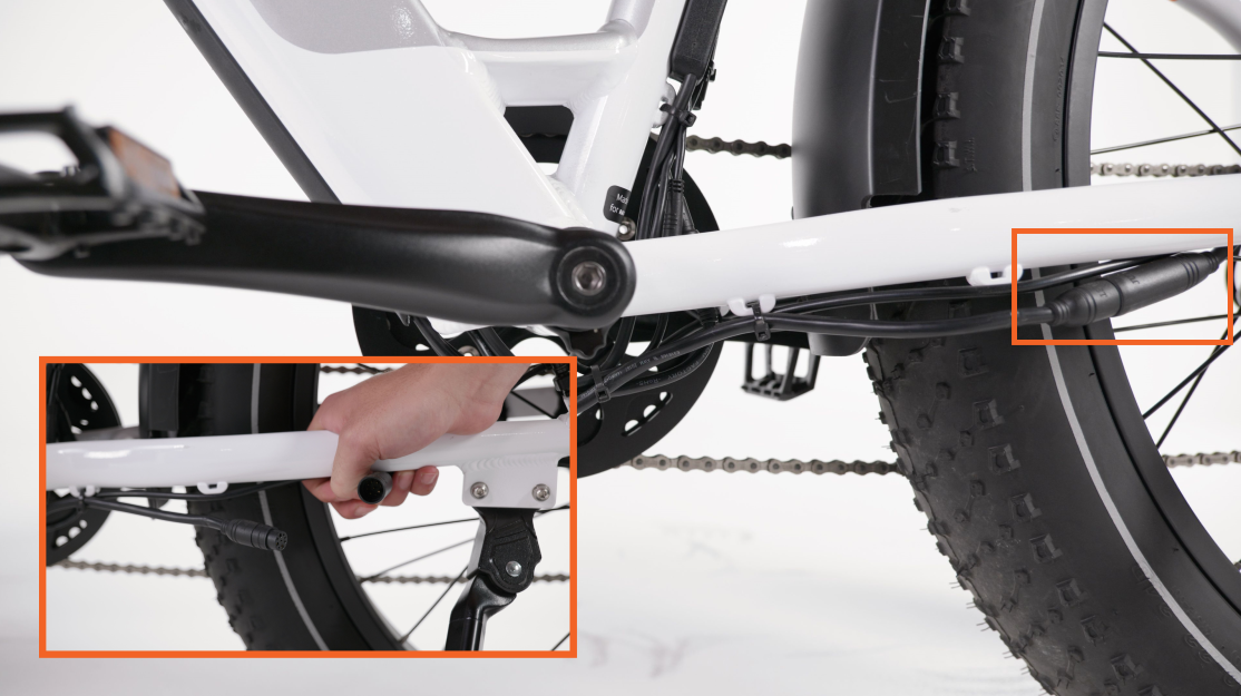
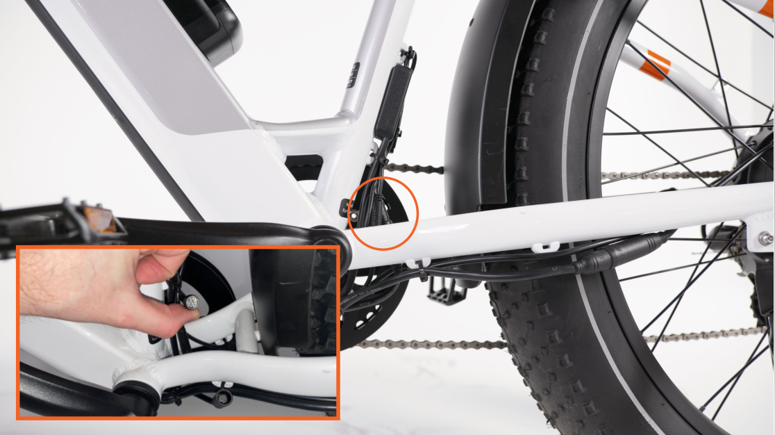
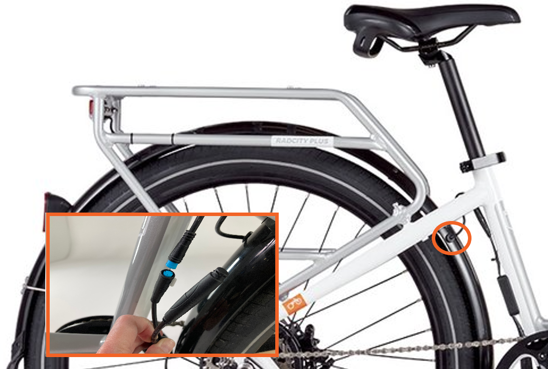
- Locate and disconnect the taillight connector. Trace the cable coming out of the front end of the rear fender (near the chainstay). Its interior is blue.
The picture above shows the taillight connector location for the RadRover 6 Plus.

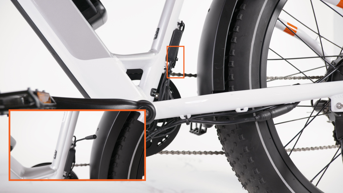
The picture above shows the taillight connector location for the RadCity 5 Plus. - Locate and disconnect the rear accessory port. It will be near the bottom of the seat tube and will have a black cap on it if it is not being used. Its interior is black.
Note: If you have any accessories attached to the accessory port, such as a USB charger, unplug the accessory by pulling the accessory port (black interior) connection apart, without twisting, and set the accessory aside. Review the accessory’s installation guide to reinstall after installing the new wiring harness (and jumper cable).
Install the new wiring harness
Locate the new wiring harness and refer to the "Before you start" section to determine if your new wiring harness has a jumper cable.
You will now install the wiring harness (with a jumper cable, if it has one), and connect all the connectors.
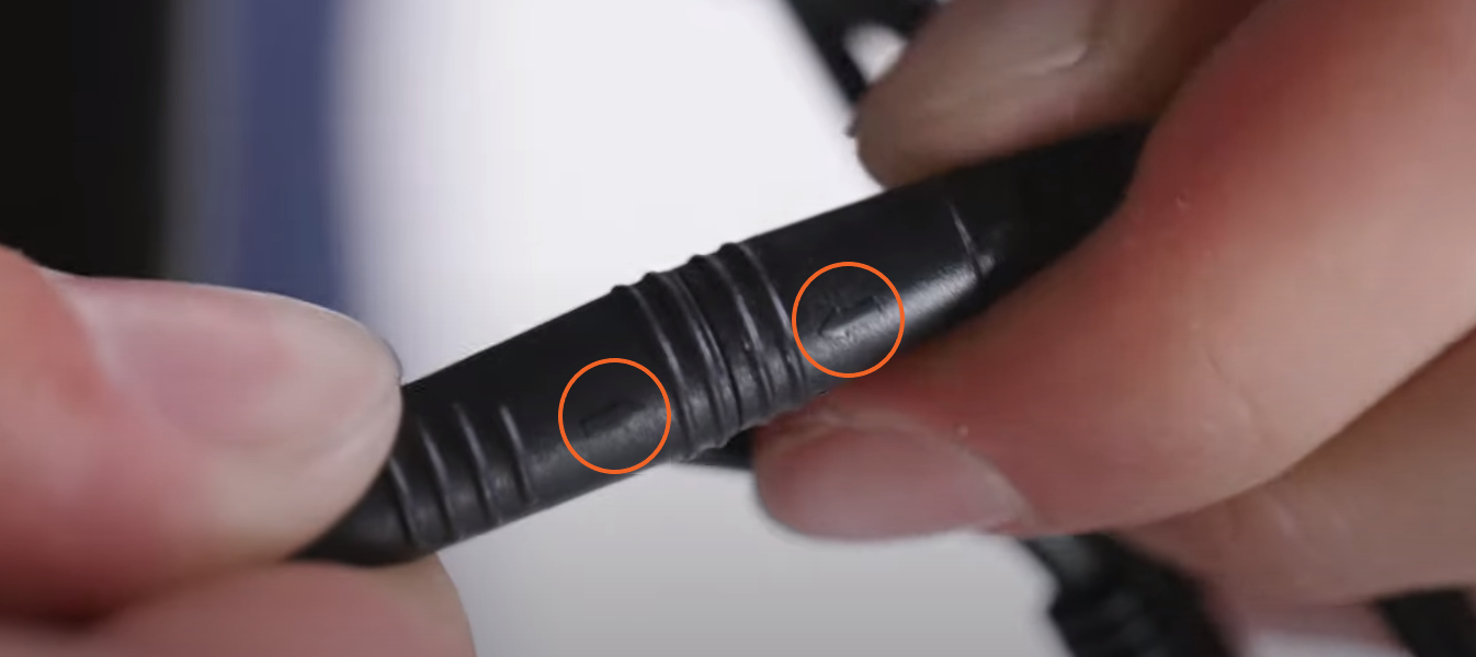
The following steps will take you through plugging in connectors near the handlebar. As you locate each connector according to the instructions, plug in the matching connector ends. Line up the internal notches and pins and press the connectors together without twisting. Refer to the image below.
Do not plug in a connector to the wiring harness if it does not match in color and shape. Doing so could cause irreparable damage to the connector, the part, or the wiring harness.
If you are installing a wiring harness with a jumper cable, connect the accessory port to the jumper cable. Make sure the arrows align, and press together without twisting. They must connect fully.
- Position the wiring harness. Orient the wiring harness so the side with the fewer connectors points downward.
- Locate and connect the Rad UI Display connector that goes to the wiring harness. There are two cables that connect to the Rad UI Display. You want the one that connects to the wiring harness (or jumper cable) and NOT to the Rad UI Remote. The interior of the connectors is green.
- Locate and connect the throttle connector. Trace the cable from the throttle on the handlebar to the connector at the front of the bike. Its interior will be orange.
- Locate and connect the left and right brake connectors. Find each of the brake connectors by tracing the cable from each brake lever on the handlebar to the connector. Its interior will be red.
- Locate and connect the headlight connector. Trace the cable from the headlight to find your headlight connector. Its interior is red.
Note: If you have any accessories that use the accessory port, such as a USB charger, review the accessory’s installation guide to reinstall it after installing the new wiring harness (and jumper cable).
The following steps take you through positioning the wiring harness and then plugging in the remaining connectors. When you connect each connector, be sure to align the internal notches and pins (and external arrows), and press them together without twisting.
- Route the wiring harness cable. Position the rest of the wiring harness so that it’s on the left side of the headtube.
- Locate and connect the wiring harness connector, by tracing the wiring harness down the downtube. Its interior will be black with 11-pins.
- Locate and connect the pedal assist-sensor (PAS) connector. Trace the cable coming out of the left crank arm (the side without the chain). Its interior is orange.
- Locate and connect the motor connector. Trace the cable coming out of the motor, at the chainstay on the bike’s left side (the side without the chain). Its interior is black with 3 pins.
- Locate and connect the taillight connector. Trace the cable coming out of the front end of the rear fender (near the chainstay). Its interior is blue.
The picture above shows the taillight connector location on the RadRover 6 Plus.
The picture above shows the taillight connector location for the RadCity 5 Plus. - Locate and connect the rear accessory port. It will be near the bottom of the seat tube, and will have a black cap on it if it is not being used. Its interior is black.
- Route the wiring harness along the right side of the external cable cover. The brake hose will be routed on the left side (the side without the chain). Seat the wiring harness between the external cable cover on the right side (the side with the chain).
- Secure the wiring harness to the frame. Rotate the handlebar to ensure it can move freely and that there is enough cable slack. Tighten the four bolts securely on the external cable protector without overtightening (start with the bolt closest to the bottom).
If your external cable cover won’t sit flush with the frame, loosen the bolts, adjust your cables, and retighten. - Check that all cables are away from any moving parts. Turn the handlebar to make sure it can move freely.
Reinstall the battery, test the bike fully, and have your work inspected by a local, certified, and reputable bike mechanic.