RadCity 5 Plus Controller Replacement Guide
Follow this guide to replace the controller on your bike in the unlikely event the controller becomes damaged or is determined to be non-functional by Rad Power Bikes Product Support. This guide will cover the installation process for the RadCity High-Step and the RadCity Step-Thru bike models.
Watch the following videos, or use the steps below to replace the controller. The controller will be located in different areas of the downtube on the High-Step and Step-Thru models, so watch the video that corresponds to your bike model.
Tools needed:
- Phillips head screwdriver
- Flat head screwdriver
- T8 Torx screwdriver
- T9 Torx screwdriver
- Flat-side cutters
- A few zip ties
- 4 mm Allen wrench
- 3 mm Allen wrench
- 2.5 mm Allen wrench
- String a few inches longer than the length of the downtube
- Electrical tape
- The replacement controller from Rad Power Bikes
Hardware may vary (bolt head style) and/or require different tools. Use the appropriate head size and type of tool for your bolts. Ensure the tool is pressed firmly into the bolt head and turn slowly to prevent stripping.
Before you start
- Get the bike ready for maintenance. Turn off the bike, remove the battery, and press the power button to discharge remaining power.
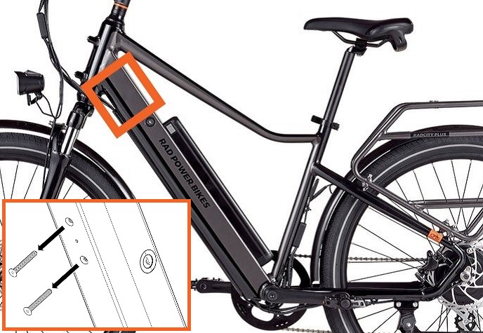
- Determine the controller location based on your bike model.
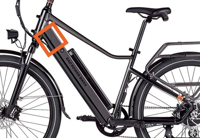 RadCity High-Step |
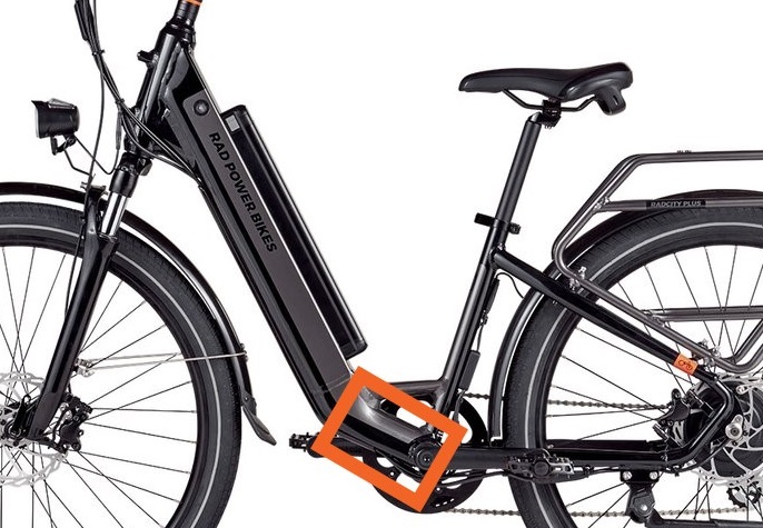 RadCity Step-Thru RadCity Step-Thru |
Remove the Old Controller
- Remove the internal cable cover. Carefully loosen all four bolts with a torx screwdriver and remove the bolts by hand. Set the internal cable cover and hardware aside.
Internal cable coverIf a bolt slips, you may need to tilt the bike so that the bolt falls out of the battery slot. There is a hole at the bottom of the downtube.
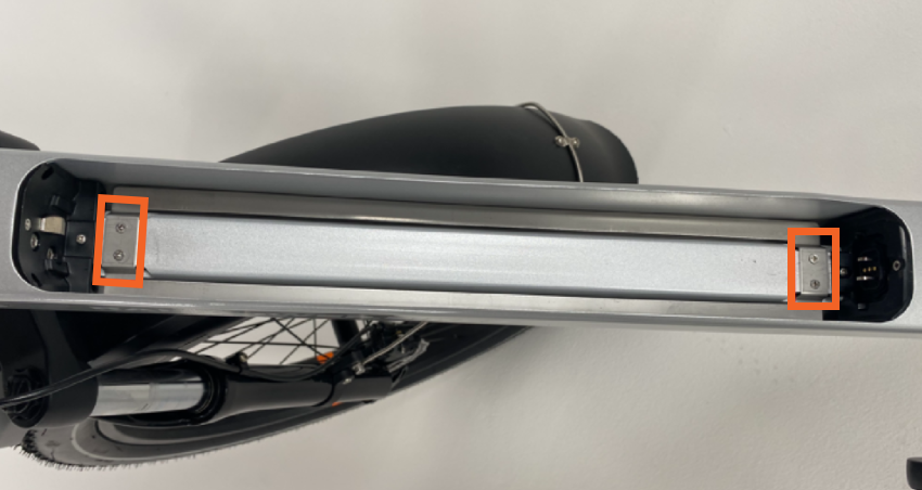
- Remove the battery mount. Use a torx screwdriver to remove the two bolts on the battery mount. Set the bolts aside for later.
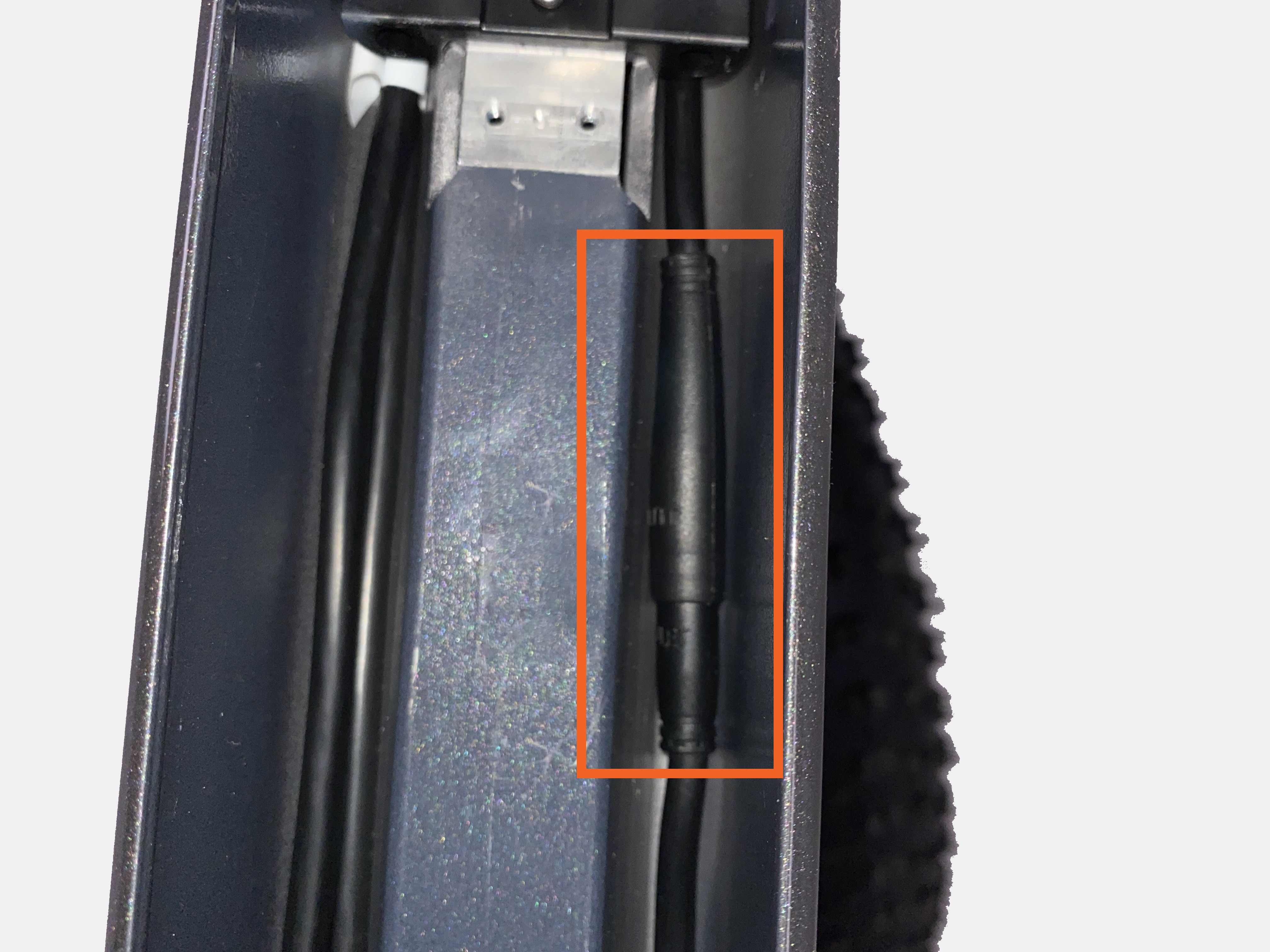
Battery mount bolts - Unplug the battery mount connector.
- The battery mount connector is directly underneath the internal cable cover in the battery slot. Pull both sides apart, without twisting, to unplug. Pull the battery mount out of the downtube and set it aside.
Battery mount connector
- The battery mount connector is directly underneath the internal cable cover in the battery slot. Pull both sides apart, without twisting, to unplug. Pull the battery mount out of the downtube and set it aside.
- Remove the lock core.
- Remove both bolts from the lock core. The bolt head style and size may vary.
Lock core bolts - Insert your key into the lock core. Turn your key clockwise toward the rear of the bike until the key hits the side of the lock core opening.
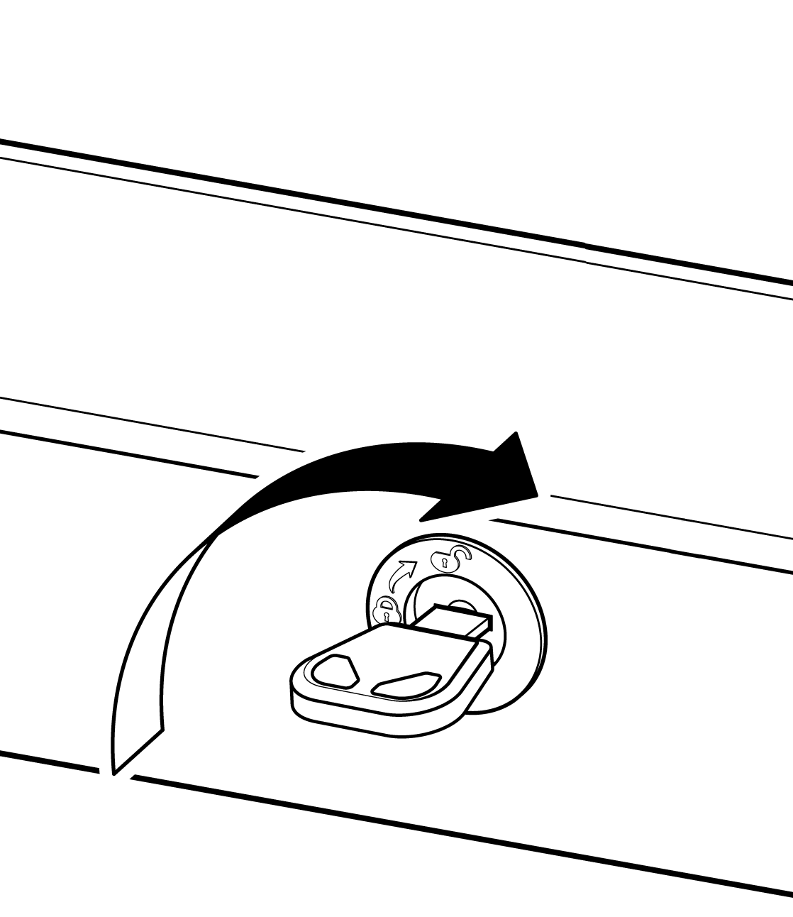
- Remove the key and pull the lock core out of the downtube. Set the lock core and the bolts aside.
- Remove both bolts from the lock core. The bolt head style and size may vary.
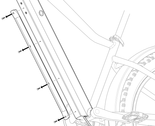
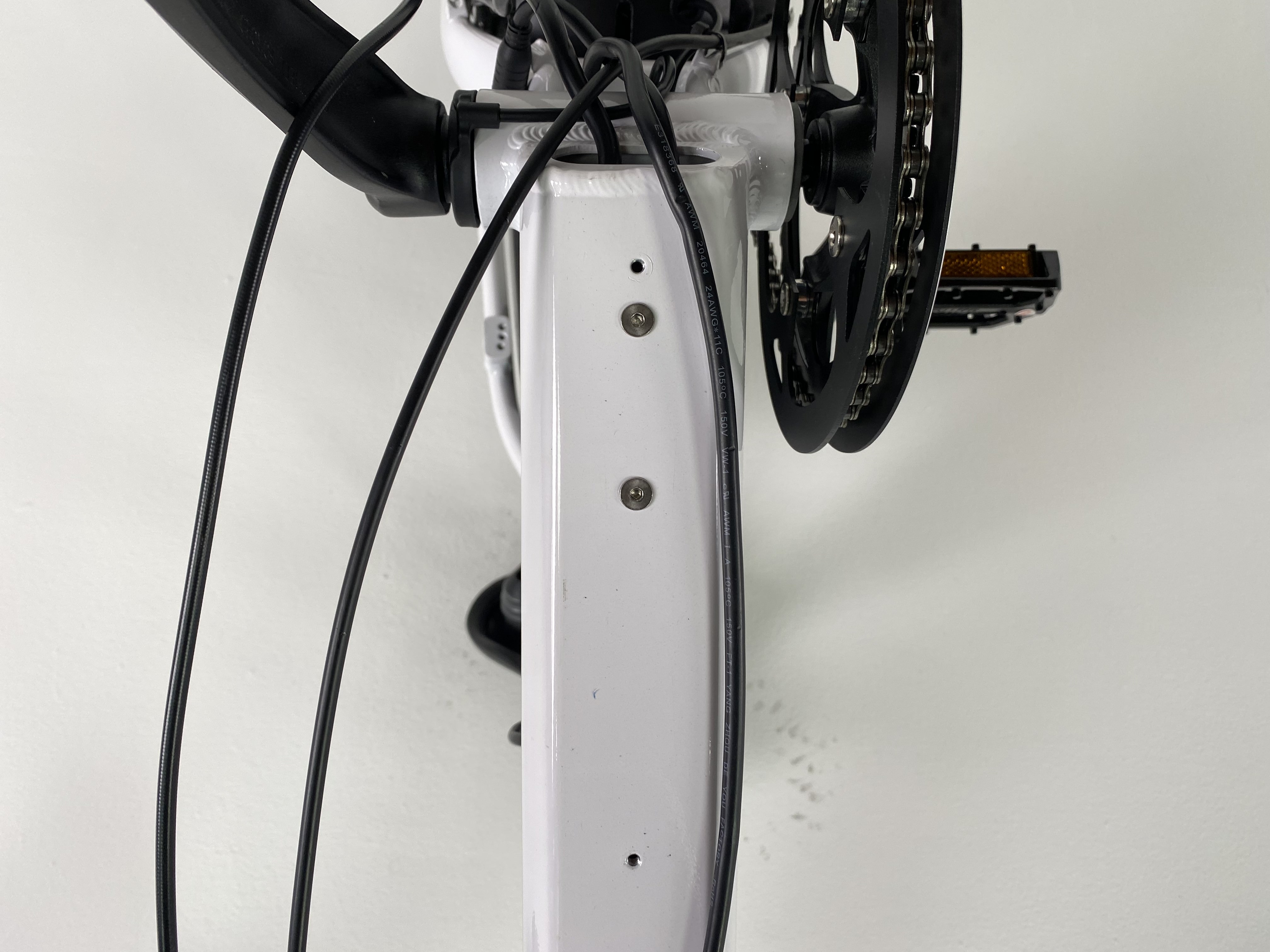
- Remove the external cable cover. Use a 2.5 mm Allen wrench to remove the four bolts underneath the downtube. Set the bolts and the external cable cover aside.
- Snip zip ties. Use flat-side cutters to snip the zip ties located near the bottom bracket and the motor cable.
- Unplug the motor connector and wiring harness connector. Pull both ends of each connector apart, without twisting, to unplug.
Motor connector Wiring harness connector
 -
Remove the grommet. Use a flat head screwdriver to unseat the grommet from the hole at the bottom of the downtube. Slide the grommet off of the motor and wiring harness cables. Set the grommet aside (it will be reinstalled later).
-
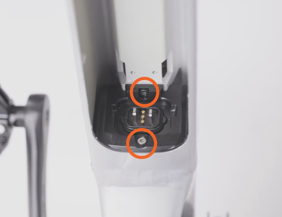
Remove the controller mounting bolts. Use your 3 mm Allen wrench to remove the controller mounting bolts.
- Remove the controller. Pull the controller out from the downtube. Set the bolts aside and recycle the old controller according to local rules.
- Remove the internal cable cover. Carefully loosen all four bolts with a torx screwdriver and remove the bolts by hand. Set the internal cable cover and hardware aside.
If a bolt slips, you may need to tilt the bike so that the bolt falls out of the battery slot. There is a hole at the bottom of the downtube
- Remove the battery mount. Use a torx screwdriver to remove the two bolts on the battery mount. Set the bolts aside for later.
- Unplug the battery mount connector.
- The battery mount connector is inside the downtube, behind the battery mount. Gently pull the battery mount until you can see the battery connector. Pull both sides apart, without twisting, to unplug. Set the battery mount aside.
- The battery mount connector is inside the downtube, behind the battery mount. Gently pull the battery mount until you can see the battery connector. Pull both sides apart, without twisting, to unplug. Set the battery mount aside.
- Remove the external cable cover. Use a 2.5 mm Allen wrench to remove the four bolts underneath the downtube. Set the bolts and the external cable cover aside.
- Snip zip ties. Use flat-side cutters to snip the zip ties located near the bottom bracket and the motor cable.
- Unplug the motor connector and wiring harness connector. Pull both ends of each connector apart, without twisting, to unplug.
Motor connector
Wiring harness connector -
Remove the grommet. Use a flat head screwdriver to unseat the grommet from the hole at the bottom of the downtube. Slide the grommet off of the motor and wiring harness cables. Set the grommet aside (it will be reinstalled later).
-
Secure the string to the controller’s connector end. Tie and tape the string to one of the controller cables at the bottom of the downtube (the string will be used to pass the new controller cables through the downtube in a later step).
Tie the string
Tape the string -
Remove the controller mounting bolts. Use a 3 mm Allen wrench to remove the controller mounting bolts.
- Remove the controller.
- Pull the controller out from the downtube, ensuring the bottom end of the string can be seen outside of the hole at the bottom of the downtube.
- Remove the end of the string attached to the old controller cables. Leave the string inside the downtube for now. (You will use this string to pull the new controller cables through the hole in a later step.)
Remove the tape
Remove the string - Set the bolts aside and recycle the old controller according to local rules.
- Pull the controller out from the downtube, ensuring the bottom end of the string can be seen outside of the hole at the bottom of the downtube.
Install the New Controller
- Prepare the controller carrier (if applicable). Some controllers will come with a controller carrier. If you do not have a controller carrier, skip to the next step.
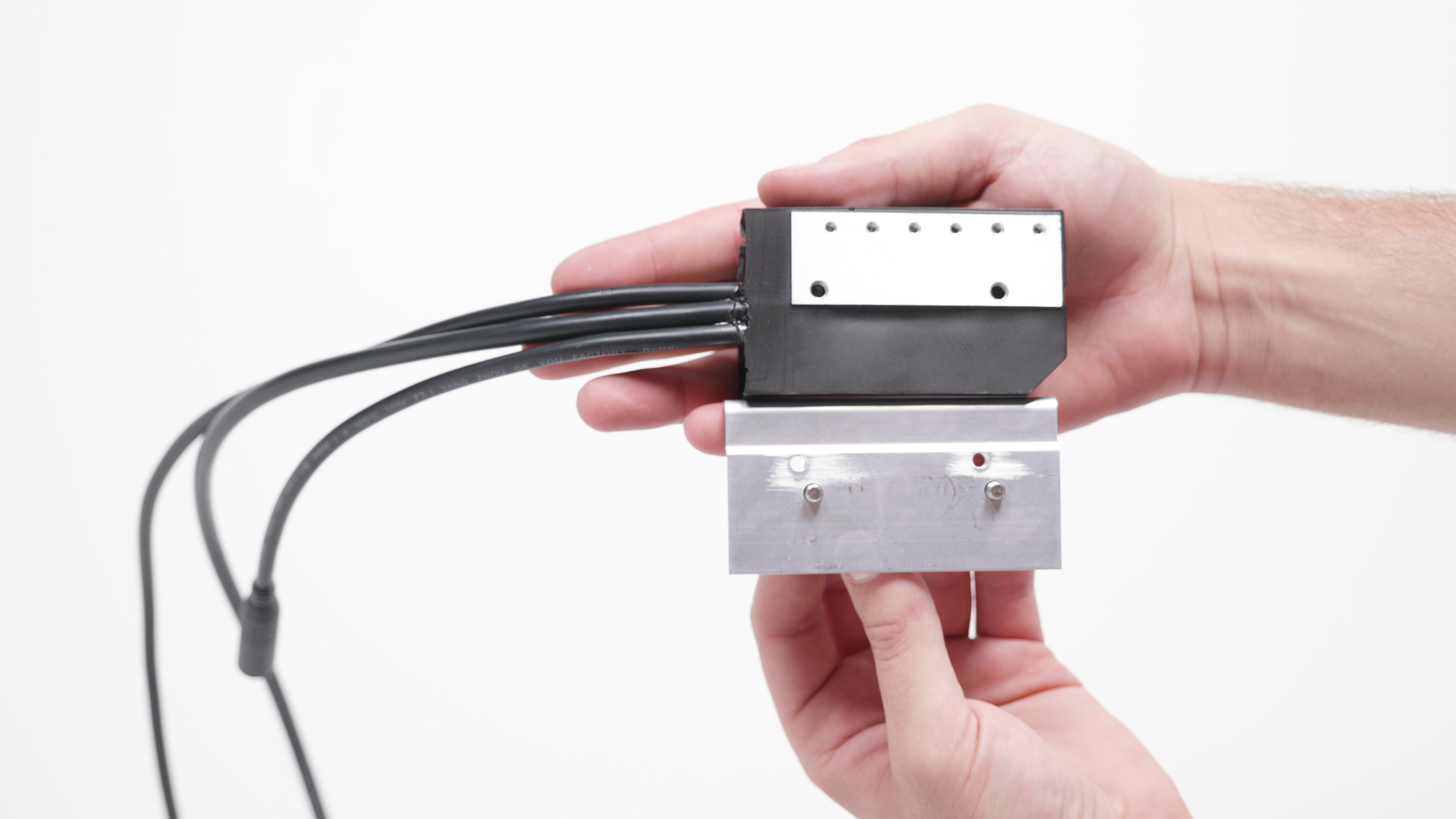
Controller with controller carrier- Lay the controller carrier horizontally on a flat surface so that the flat side faces upward. Set the flat side of the controller on top of the controller carrier.
Controller on the controller carrier - Turn the controller and carrier upside down so that the bolt holes face upward. Align the holes on the carrier with the holes on the controller.
- Using an Allen wrench, thread the controller carrier bolts through the carrier, into the controller until secure. Do not overtighten.
- Lay the controller carrier horizontally on a flat surface so that the flat side faces upward. Set the flat side of the controller on top of the controller carrier.
- Prepare the new controller.
- Insert the controller into the battery slot. Ensure the controller holes are facing downward and the cables are facing the rear of the bike.
- Push the ends of the wiring harness and motor connectors through the hole at the bottom of the downtube until both connectors hang outside of the frame.
- Insert the controller into the battery slot. Ensure the controller holes are facing downward and the cables are facing the rear of the bike.
- Attach the controller.
- Align the controller holes with the holes in the frame.
- If you have a controller carrier, the bolts will thread through the mounting holes in the frame, through the carrier, and into the controller.
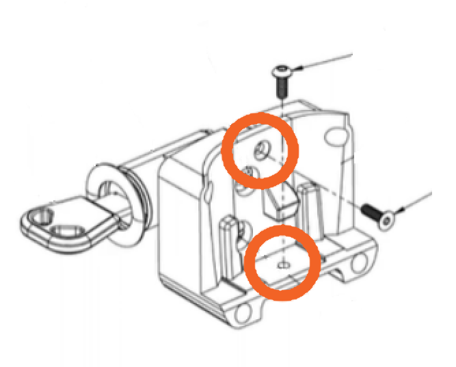
- If you have the LD.CR.S607 model controller, use the two mounting points shown below.
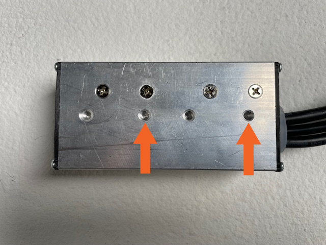
- Thread in the bolts by hand, then tighten each bolt using a 3 mm Allen wrench. Torque to 5 Nm.
- Align the controller holes with the holes in the frame.
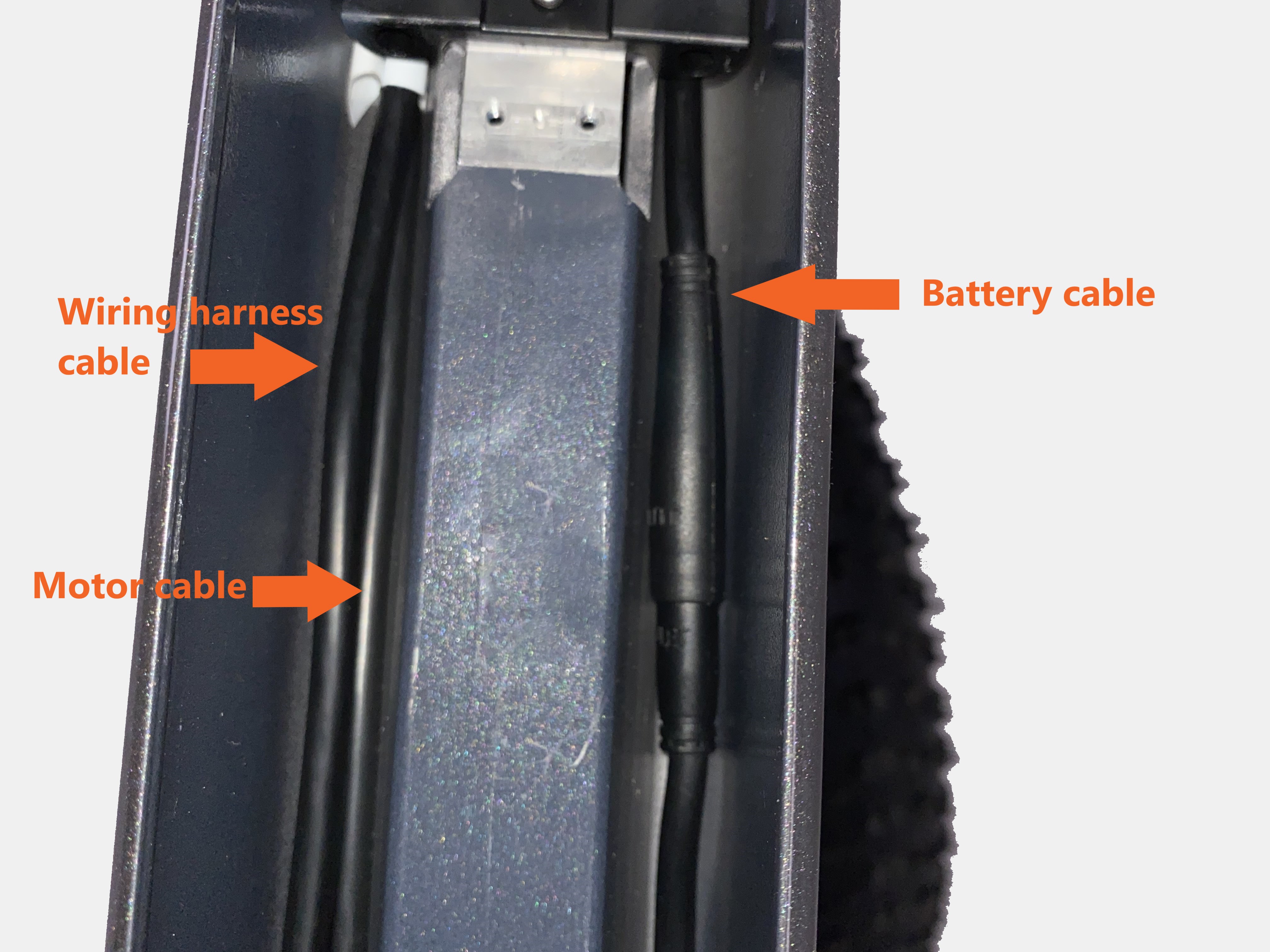
- Route the controller cables.
- Route the motor and wiring harness cables along the non-drive side (the side of the bike without the chain) of the downtube.
- Route the battery cable on the drive side (the side of the bike with the chain) of the downtube.

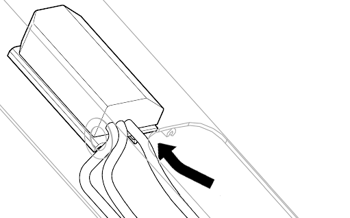
- Reinstall the grommet. Slide the grommet over the controller’s motor and wiring harness cables at the bottom of the downtube. Seat the grommet back into the hole at the bottom of the downtube.
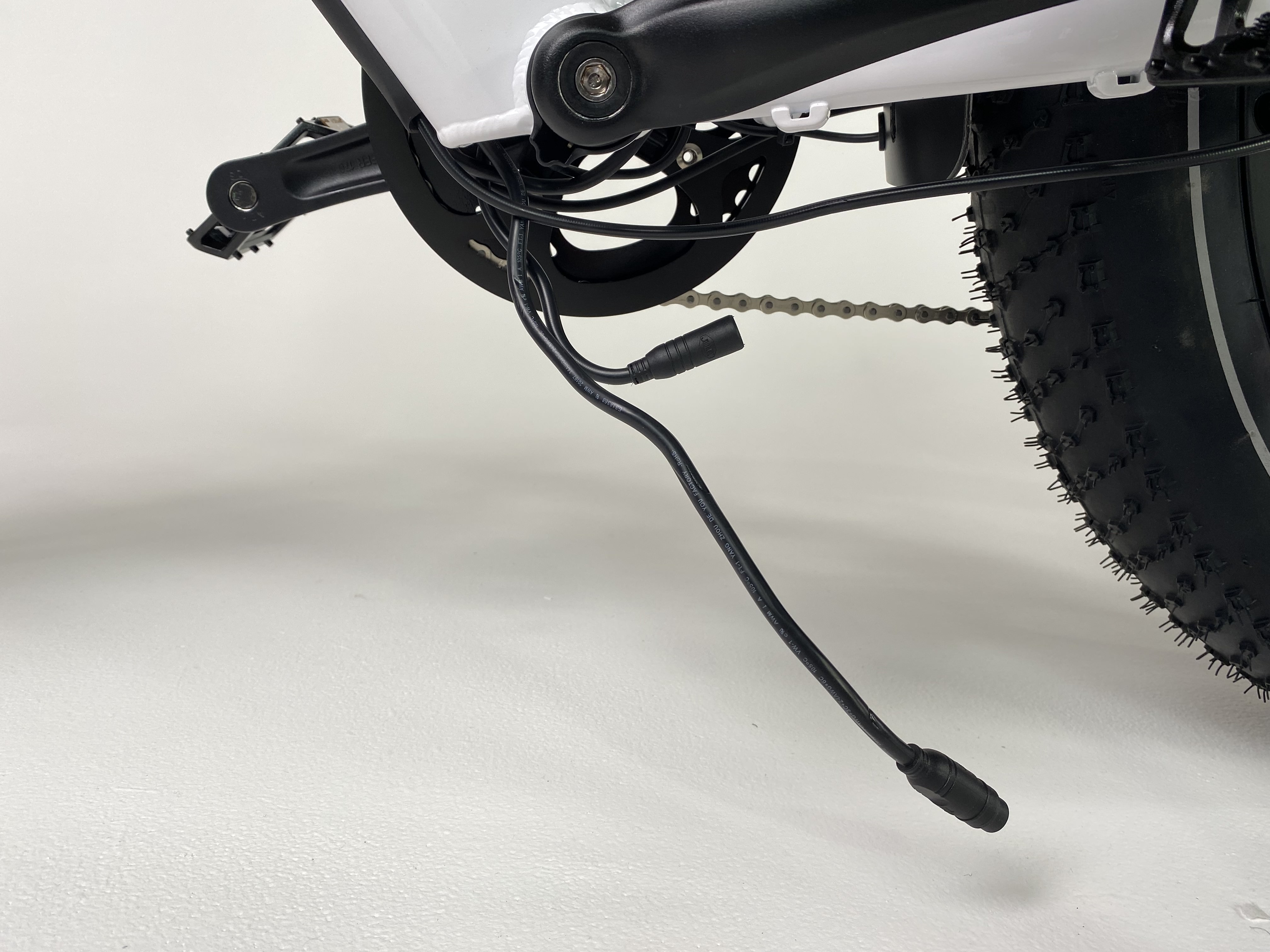
- Plug in the motor and wiring-harness connectors. At the bottom of the downtube, locate the matching connector ends. The wiring harness connector has 11 internal pins and the motor has 3 internal pins. Align the internal notches and pins and external arrows. Press both ends together, without twisting, to connect.
Motor connector Wiring harness connector
 -
Plug in the battery mount connector. Locate the battery mount and connect it to the controller inside the downtube. Line up the internal notches and pins, and external arrows, and press together without twisting.
-
Install the battery mount. Thread in each bolt using a torx screwdriver. Tool size may vary between the two bolts. Torque to 2 Nm.
If a bolt slips, you may need to tilt the bike so that the bolt falls out of the battery slot. There is a hole at the bottom of the downtube.
- Install the lock core.
- Place the lock core into position. The lock cylinder must face the non-drive side of the bike.
- Ensure all cables sit flush underneath the lock core.
- Thread in both bolts by hand. Use a torx screwdriver to tighten both bolts until secure. Do not overtighten. Tool size may vary between the two bolts.
If a bolt slips, you may need to tilt the bike so that the bolt falls out of the battery slot. There is a hole at the bottom of the downtube.
- Install the internal cable cover. Place the internal cable cover into position, making sure not to pinch any cables. Thread in the four bolts by hand, and use a torx screwdriver to evenly tighten the four bolts until secure. Do not overtighten.
Internal cable cover - Replace snipped zip ties. Use flat-side cutters to snip off zip tie excess. Ensure the cut is flush and smooth with no sharp point.
- Install the external cable cover.
- Place the external cable cover in position underneath the frame.
- Thread in all four bolts by hand, starting with the bolt closest to the bottom bracket.
- Position the wiring-harness cable (the thickest cable) on the drive side (the side of the bike with the chain) of the external cable cover bolts. Tuck the wiring harness cable into the external cable cover.
- Position the shifter and brake cables on the non-drive side (the side of the bike without the chain) of the external cable cover bolts. Tuck the shifter cable and brake cable into the external cable cover.
- Use a 2.5 mm Allen wrench to evenly tighten all four bolts until secure, starting with the bolt closest to the bottom bracket. Do not overtighten.
- If the external cable cover does not sit flush with the frame, loosen all four bolts, one at a time. Ensure that no cables are pinched between the external cable cover and the frame. Re-tighten all four bolts with a 2.5 mm Allen wrench.
- Check that all cables are out of the way of moving parts. Turn the handlebar to each side to ensure it can move freely.
- Reinstall the battery and test the bike fully before riding.
|
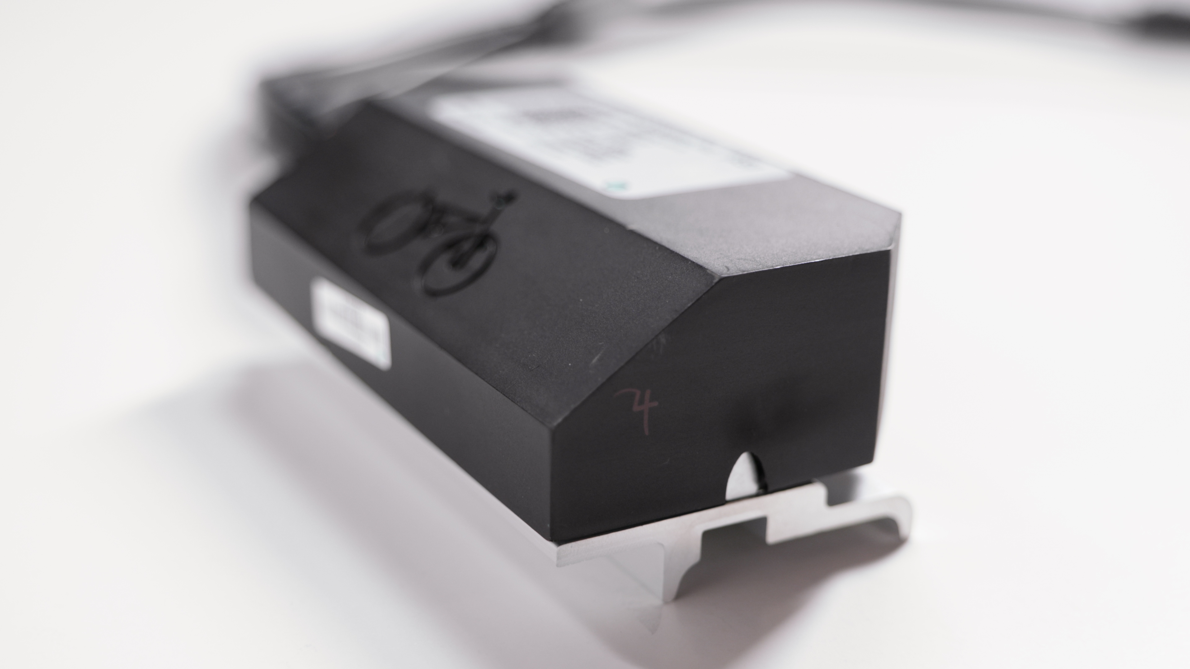
Model BAC355 |
Model LD.CR.S607 |
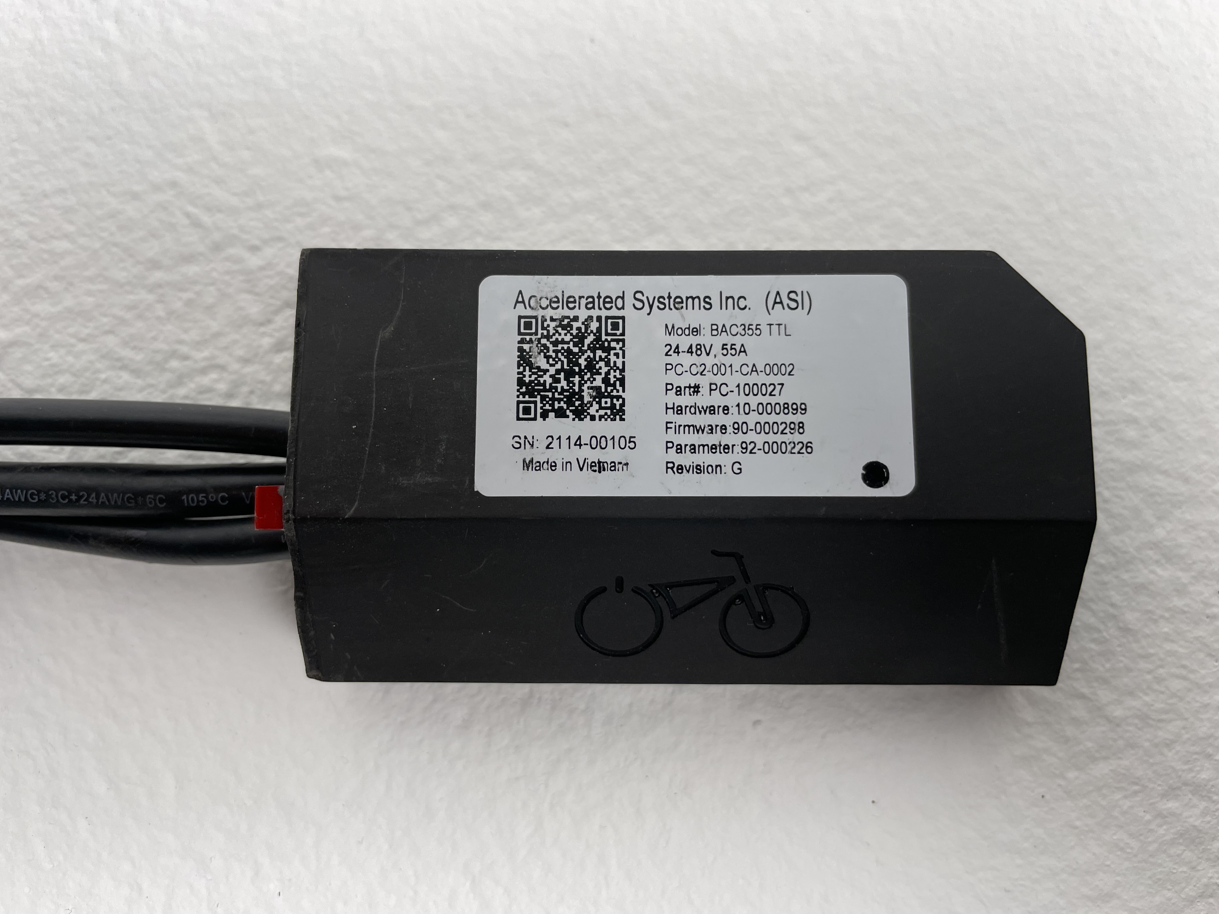
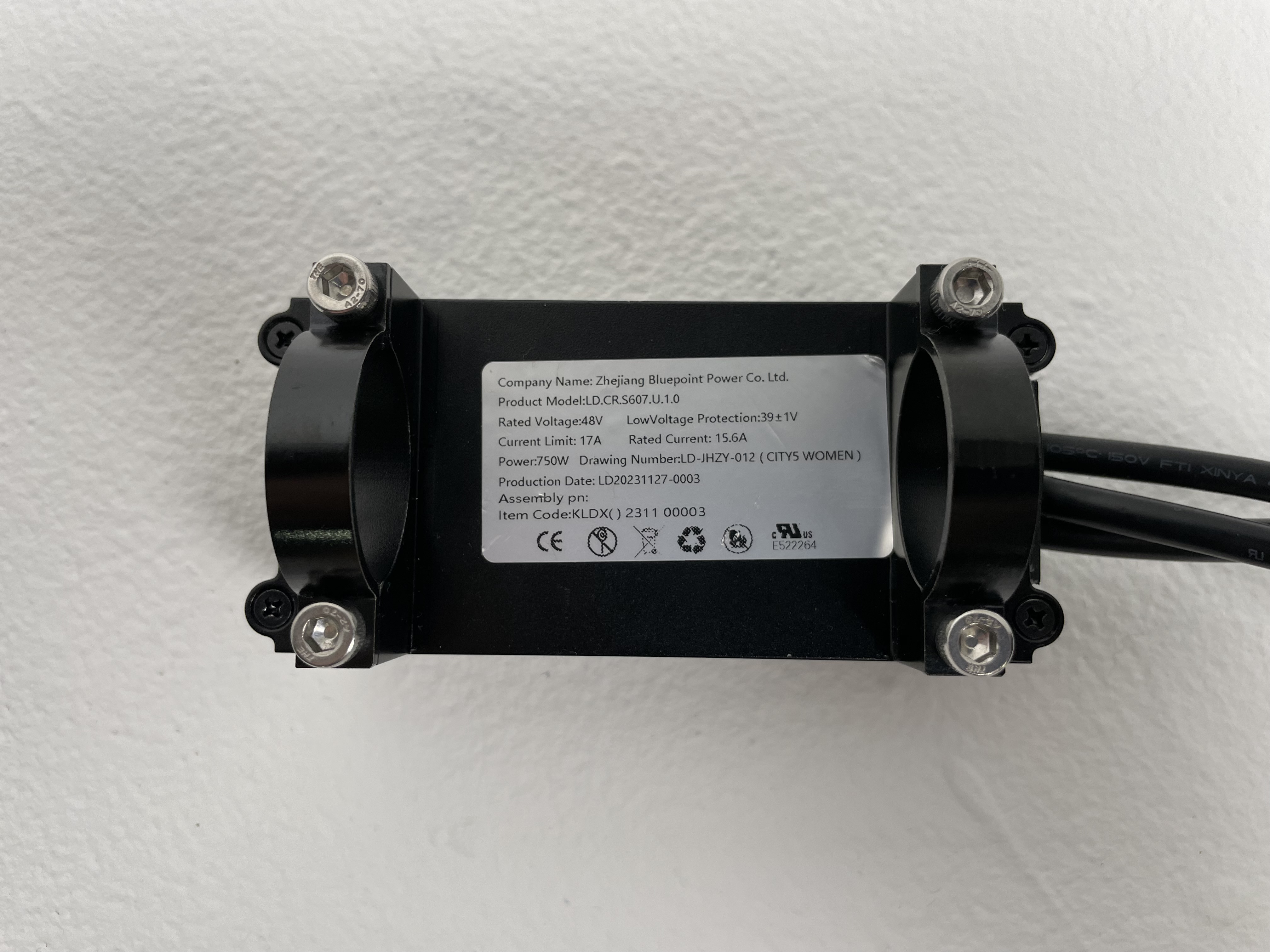
- Identify the replacement controller. If you received the BAC355 model controller (left), go to step 2 for the steps to mount that model. If you received the LD.CR.S607 model controller (right), skip to step 6 for the steps to mount that model.
- Prepare the new controller to mount inside frame downtube.
- Bend the motor cable and wiring harness cable back around the controller so that they face the rear of the bike.
- Optional: Secure the wiring harness cable and motor cable to the controller with a strip of electrical tape.
Ensure none of the controller holes are covered by tape. The silver portion of the controller acts as a heat sink and must be free from obstruction. If there is tape covering any of the holes on your controller, remove the tape and reapply until all holes are completely uncovered.
- Secure the top end of the string around the wiring harness and motor cables. Use a strip of electrical tape to secure the string to each connector end.
- Bend the motor cable and wiring harness cable back around the controller so that they face the rear of the bike.
- Route the cables.
- Set the controller down in the battery slot. Position the controller with the bolt holes facing downward. The motor cable and wiring harness cable must both face the rear of the bike.
- Lower the controller into the secondary compartment in the downtube.
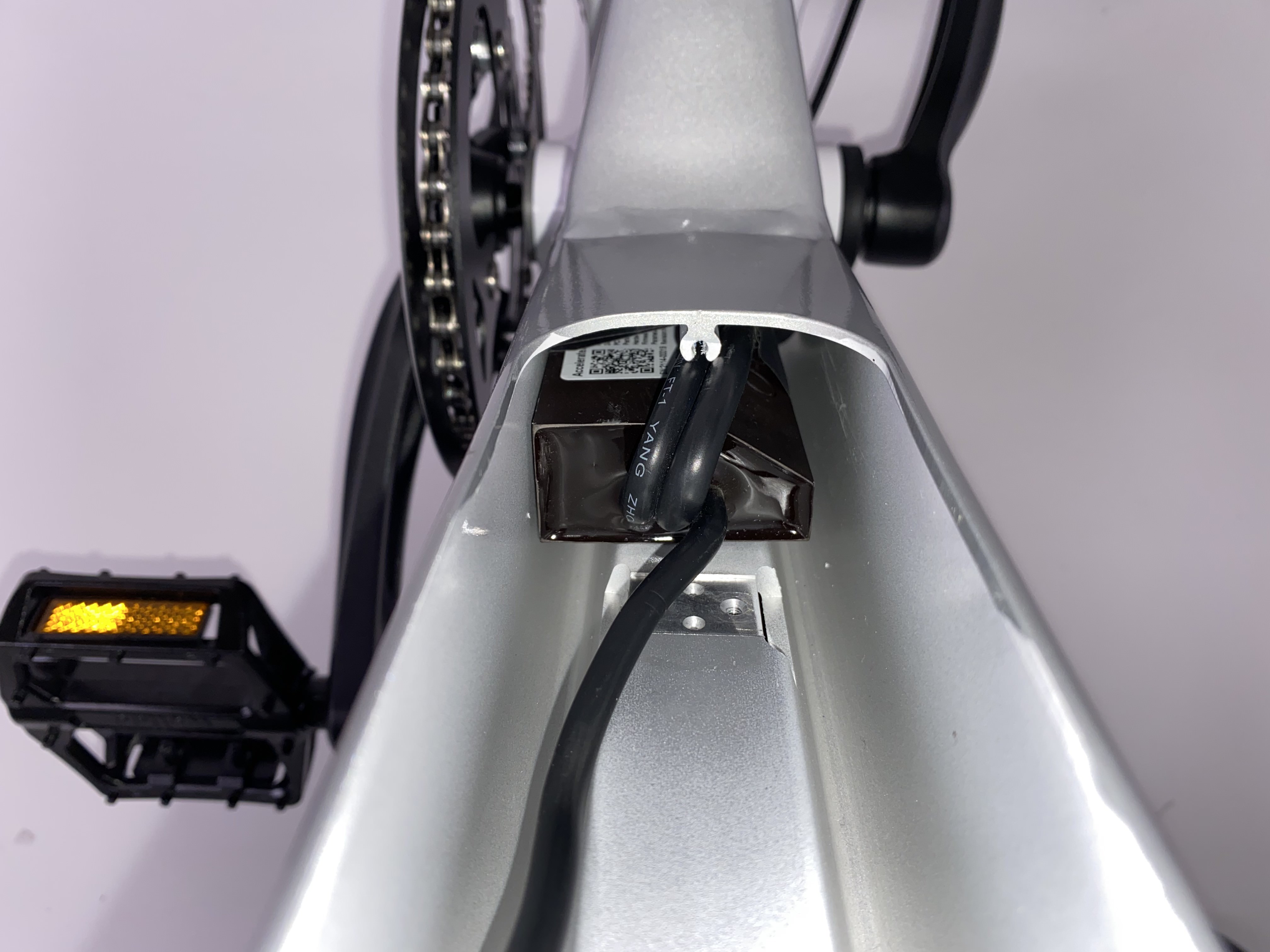
- Pull the bottom end of the string to guide the cables through the hole at the bottom of the downtube until both connector ends are visible outside of the frame.
- Set the controller down in the battery slot. Position the controller with the bolt holes facing downward. The motor cable and wiring harness cable must both face the rear of the bike.
- Attach the controller.
- Align the controller bolt holes with the holes on the frame. Ensure the controller is fully seated within the secondary compartment in the downtube.
- Thread the controller mounting bolts by hand, passing them through the frame’s mounting holes and into the controller. Tighten each bolt using a 3 mm Allen wrench. Torque to 5 Nm.
- Remove the electrical tape from the connector ends. Remove the string from the controller cables.
- Align the controller bolt holes with the holes on the frame. Ensure the controller is fully seated within the secondary compartment in the downtube.
- Reinstall the grommet. Slide the grommet over the controller’s motor and wiring harness cables at the bottom of the downtube. Seat the grommet back into the hole at the bottom of the downtube.
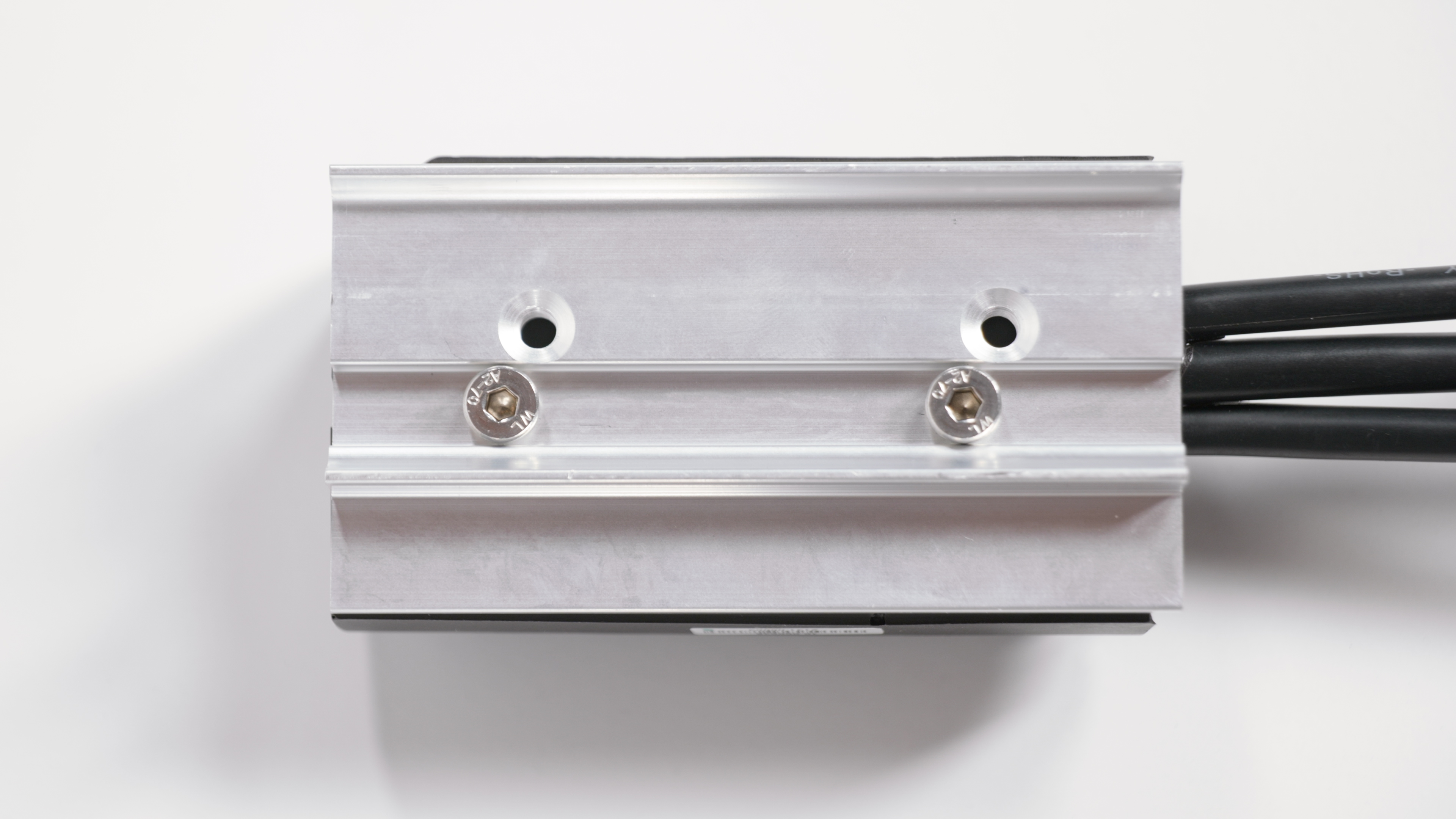
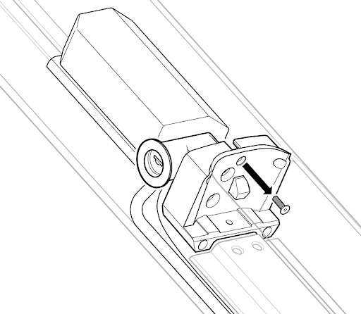
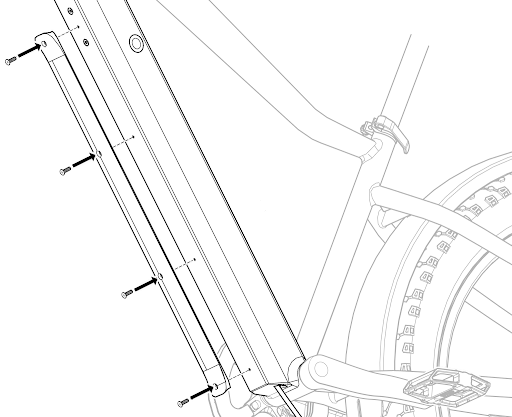
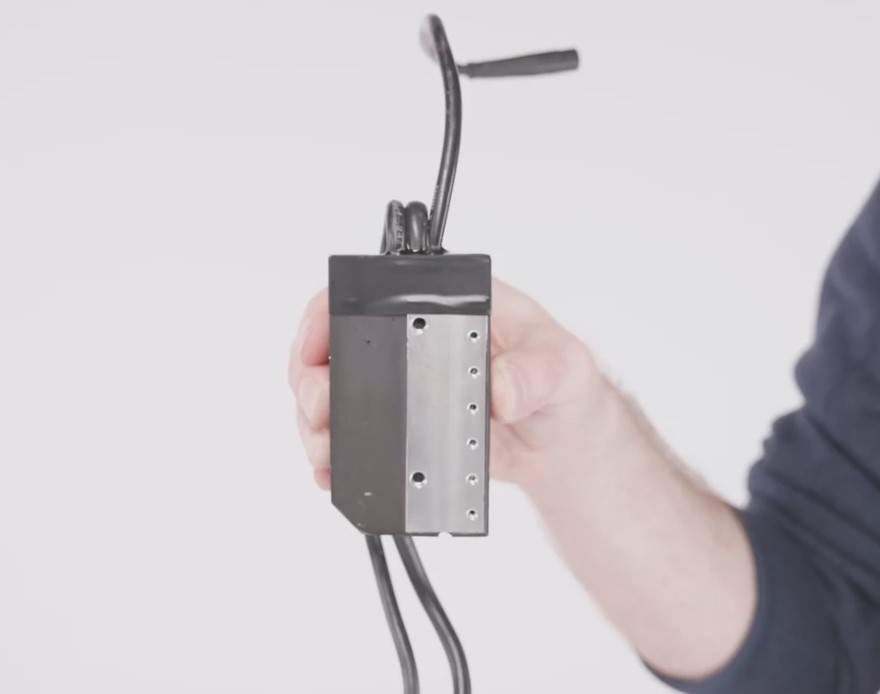
- Mount the controller on the seat tube. If you received the LD.CR.S607 model controller, mount to the seat tube as follows:
- Use flat side cutters to disconnect the wiring harness junction box currently mounted on the seat tube. You will remount this after the new controller is in place.
- Use a 4 mm Allen wrench to remove the controller mounting brackets.
- Position the controller on the seat tube, facing the rear of the bike (see below).
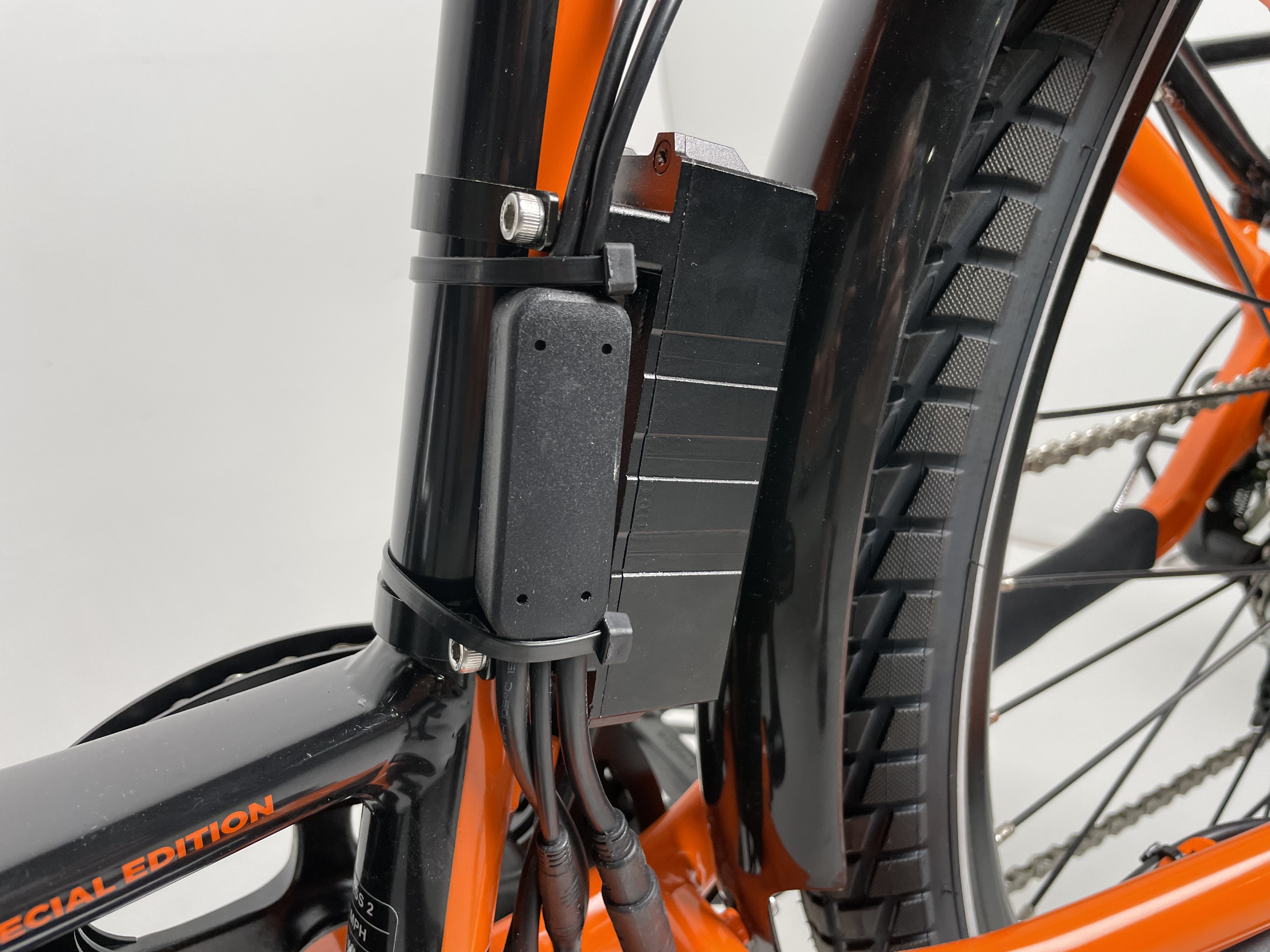
- Use the 4 mm Allen wrench to reinstall the mounting brackets until secure.
- Position the wiring harness junction box on the side of the controller between the mounting brackets, and use zip ties to secure to the seat tube.
- Use flat side cutters to snip off zip tie excess. Ensure the cut is flush and smooth, with no sharp point.
- Route the controller cables through the frame opening at the bottom of the seat tube.
- Plug in the motor and wiring harness connectors. At the bottom of the downtube, locate the matching connector ends. The wiring harness connector has 11 internal pins and the motor has 3 internal pins. Align the internal notches and pins and external arrows. Press both ends together, without twisting, to connect.
Motor connector
Wiring harness connector -
Plug in the battery mount connector. Locate the battery mount and connect it to the controller inside of the downtube. Line up the internal notches and pins, and external arrows, and press together without twisting.
-
Install the battery mount. Using a Torx screwdriver, thread the two bolts back into the battery mount until secure. Tool size may vary between the two bolts. Do not overtighten.
If a bolt slips, you may need to tilt the bike so that the bolt falls out of the battery slot. There is a hole at the bottom of the downtube.
-
Install the internal cable cover. Place the internal cable cover into position, making sure not to pinch any cables. Thread in the four bolts by hand, and use a Torx screwdriver to evenly tighten the four bolts until secure. Do not overtighten.
-
Replace snipped zip ties. Use flat-side cutters to snip off zip tie excess. Ensure the cut is flush and smooth, with no sharp point.
- Install the external cable cover.
- Place the external cable cover in position underneath the frame.
- Thread in all four bolts by hand, starting with the bolt closest to the bottom bracket.
- Position the wiring harness cable (the thickest cable) on the drive side (the side with the chain) of the external cable cover bolts. Tuck the wiring harness cable into the external cable cover.
- Position the shifter and brake cables on the non-drive side (the side without the chain) of the external cable cover bolts. Tuck the shifter cable and brake cable into the external cable cover.
- Use a 2.5 mm Allen wrench to evenly tighten all four bolts until secure, starting with the bolt closest to the bottom bracket. Do not overtighten.
- If the external cable cover does not sit flush with the frame, loosen all four bolts, one at a time. Ensure that no cables are pinched between the external cable cover and the frame. Re-tighten all four bolts with a 2.5 mm Allen wrench.
- Check that all cables are out of the way of moving parts. Turn the handlebar to each side to ensure it can move freely.
- Reinstall the battery and test the bike fully before riding.