RadRover 6 Plus (2021) error 30 / connector check guide
Checking the connectors and ensuring they are secure and undamaged can help diagnose electrical issues and make sure your ebike is safe and fun to ride.
|
Error code on RadUI Remote |
Error code on RadUI Display |
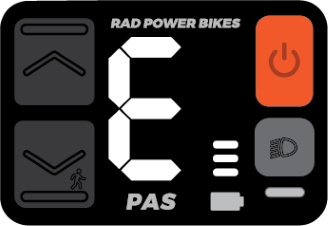

Over time, a connector on your ebike may vibrate loose and need to be plugged in again. If that happens, you may receive an error message or the bike may fail to power on. Performing a connector check can help solve the problem.
Overview
The process will require you to power off the bike, remove the battery, discharge residual power, unplug a connector and inspect it (take photos of any signs of moisture, debris, or damage), carefully plug the connector back in, turn on the battery, and check if the issue is resolved when you power on the bike. Repeat the process for each connector until the issue is resolved.
Tools needed:
- Flat side cutters to snip zip ties securing the connector cables,
- A camera to take photos of any moisture, debris, or damage for Rad Power Bikes Product Support,
- A 2.5 mm Allen wrench,
- Phillips head screwdriver, and
- Replacement zip ties to secure the cables once the process is complete
Before you start
- Prepare your bike for maintenance. Turn off the bike, remove the battery, and press and hold the power button to discharge remaining power.
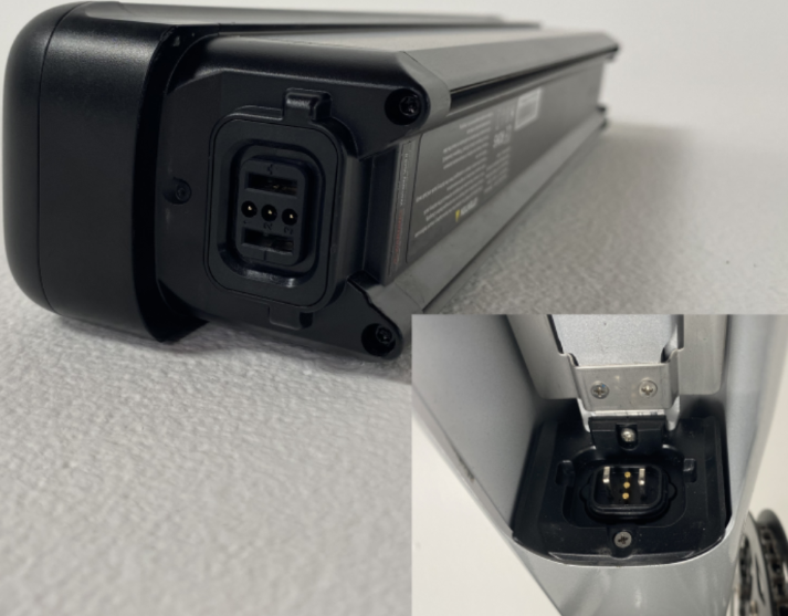
- Inspect the battery and battery mount terminal contacts. If the contacts are damaged, dirty, or wet, the part may need to be replaced. Take a photo and contact Product Support for help. If the contacts are in good condition, set the battery aside for now.
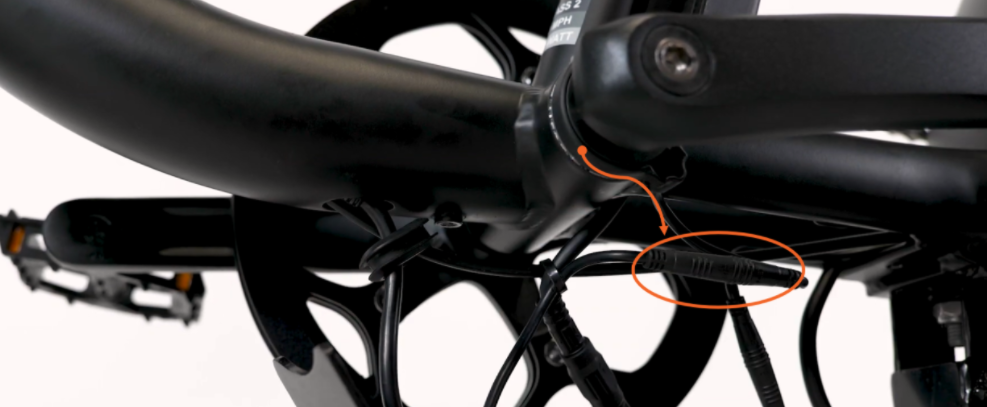
NOTICE: Do not drop the battery or touch/damage the connector terminals when the battery is removed. - Determine whether your bike has a jumper cable. The jumper cable is an extra piece of cable that some bikes have incorporated into the wiring harness as shown in the second illustration below. Whether or not you have a jumper cable will affect which connector check steps apply to you.
- If your accessory cable doesn't connect with anything (it has a cap on its end), you do not have a jumper cable.
- If the accessory cable loops back up toward your wiring harness and connects to another cable, you do have a jumper cable.
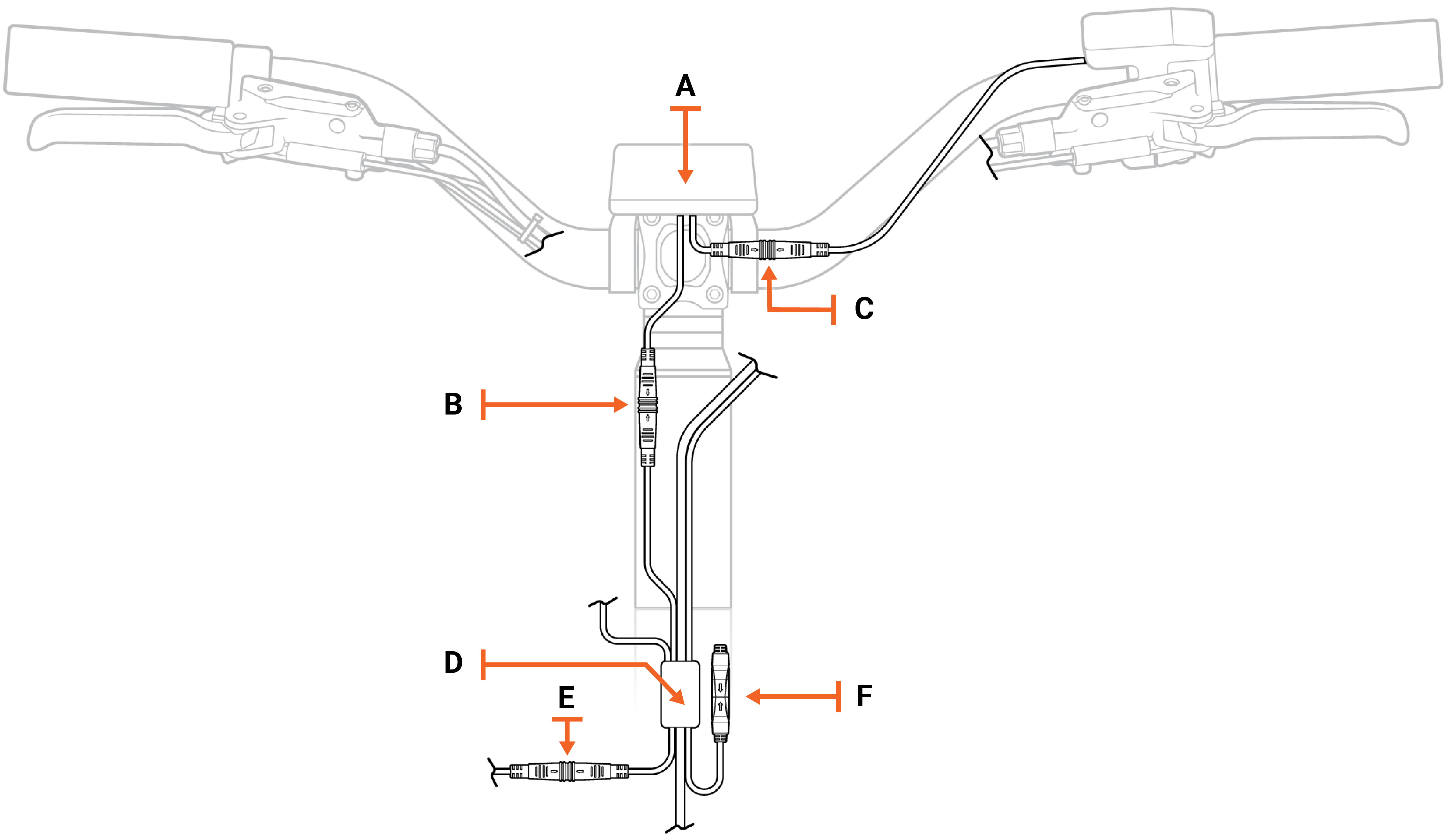
Above: Wiring harness without a jumper cable
Legend (for wiring harness illustrations above and below)
| A | Rad UI Display |
| B | Rad UI Display connector to the wiring harness (on bikes without a jumper cable). On bikes with a jumper cable, this connector connects to the jumper cable. |
| C | Rad UI Display connector to the Rad UI Remote |
| D | Wiring harness junction |
| E | Wiring harness to headlight connector |
| F | Accessory port with connector cover on its end |
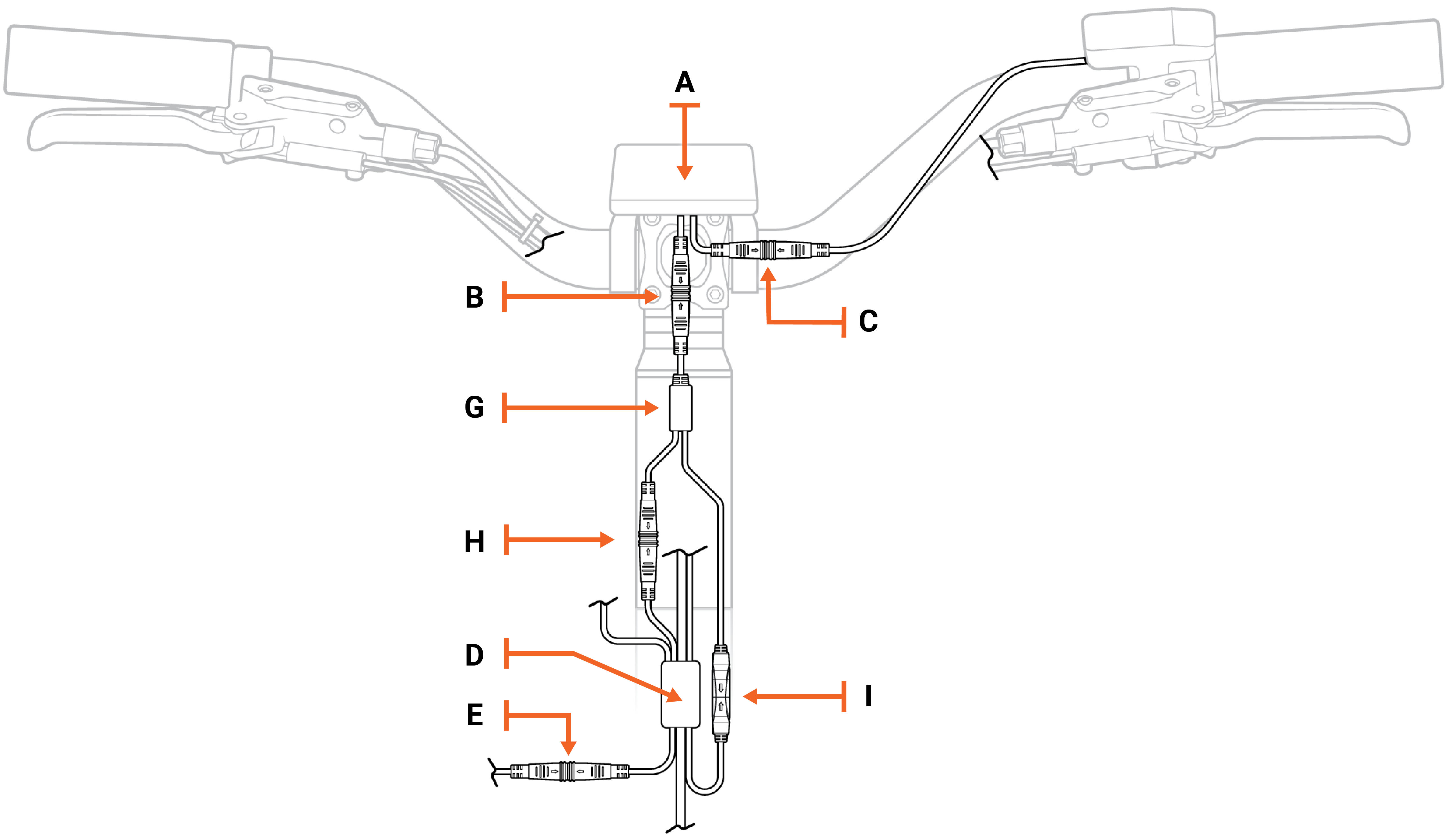
| G | Jumper cable junction |
| H | Jumper cable connected to the wiring harness |
| I | Jumper cable connected to the accessory port |
Below: Wiring harness with a jumper cable
Checking individual connectors
There are a few main connectors that can cause an error if they are loose or damaged.
- Rad UI Display connectors
- Wiring harness connector
- Battery connector
You will unplug one connector at a time, inspect the inside, reconnect it, and turn on the bike to see if the error is resolved. As you work through the connectors, use flat-side cutters to snip zip ties as needed to create enough slack to unplug the connector.
Click on each heading below and follow the instructions within to check each connector.
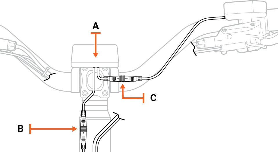
In this step, you will check the Rad UI connectors that go to the jumper cable and to the Rad UI remote. Refer to the diagram below.
| A | Rad UI Display |
| B | Rad UI Display connector to the jumper cable |
| C | Rad UI Display connector to the Rad UI Remote |
| H | Jumper cable connector to the wiring harness |
- Locate the Rad UI Display connector ("C" in the illustration above) that goes to the Rad UI Remote by tracing the cable that goes between those two components. Pull each side of the connectors apart without twisting. Snip zip ties if you need more cable slack.
- Locate the Rad UI Display connector ("B" in the illustration above) that goes to the jumper cable. There are two cables connected to the Rad UI Display. You just traced one of them to the Rad UI Remote. The other cable connects to the jumper cable. Disconnect this connector by pulling it apart without twisting.
- Locate the jumper cable connector ("H" in the illustration above) that goes to the wiring harness. Trace the connector that has been disconnected from the Rad UI to the jumper cable. At the fork the jumper cable leads to the accessory port (labeled "I") and the wiring harness (labeled "H"). Disconnect the connector that is identical in size and color (green) to the Rad UI.
- Inspect the inside of the connectors.
- If the inside is damaged, dirty, or wet, the part may need to be replaced. Take a photo and contact Product Support for help.
- If the inside of the connector is in good condition, line up the internal notch and pins and external arrows, and press together without twisting to reconnect.
- Reinstall the battery and turn on the bike. If the error continues, turn off the bike, remove the battery, and discharge remaining power. We’ll repeat this process with the wiring harness connector and then the battery connector.
In this step, you will check the Rad UI connectors that go to the wiring harness and to the Rad UI remote. Refer to the diagram below.
| A | Rad UI Display |
| B | Rad UI Display connector to the wiring harness |
| C | Rad UI Display connector to the Rad UI Remote |
- Locate the Rad UI Display connector ("C" in the illustration above) that goes to the Rad UI Remote by tracing the cable that goes between those two components. Pull each side of the connectors apart without twisting. Snip zip ties if you need more cable slack.
- Locate the Rad UI Display connector ("B" in the illustration above) that goes to the wiring harness. There are two cables connected to the Rad UI Display. You just traced one of them to the Rad UI Remote. The other cable connects to the wiring harness. Disconnect this connector by pulling it apart without twisting.
- Inspect the inside of the connectors.
- If the inside is damaged, dirty, or wet, the part may need to be replaced. Take a photo and contact Product Support for help.
- If the inside of the connector is in good condition, line up the internal notch and pins and external arrows, and press together without twisting to reconnect.
- Reinstall the battery and turn on the bike. If the error continues, turn off the bike, remove the battery, and discharge remaining power. We’ll repeat this process with the wiring harness connector and then the battery connector.
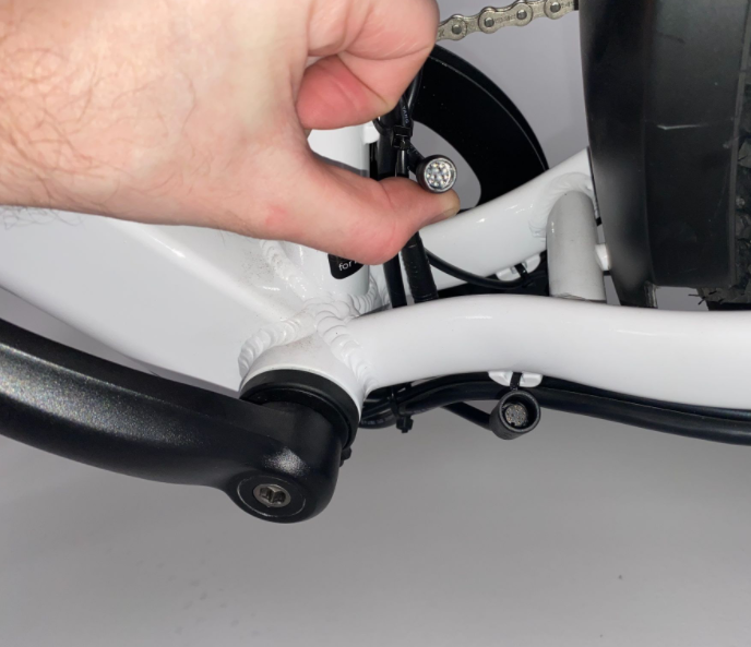
- To check the wiring harness connector, partially loosen the bolts on your external cable cover, and turn the handlebar to the left to create cable slack.
- Locate the wiring harness connector just behind the bottom of the seat tube. Unplug it and inspect the inside. The 11 pins must be clean and not bent. If it looks normal, line up the internal notch and pins, and external arrows, and press together without twisting to reconnect.
- Double-check that the connector is secure.
- At the top of the downtube, gently pull the wiring harness cable to create cable slack at the front of the bike. Ensure the handlebar turns to both sides before tightening the bolts on the external cable cover.
- Reinstall the battery and turn on the bike. If the error continues, turn off the bike, remove the battery, and discharge remaining power. Then move on to the battery connector.
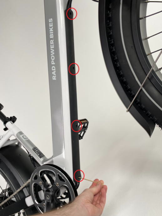
- Remove the four bolts on the internal cable cover using your Phillips head screwdriver, and set them aside.
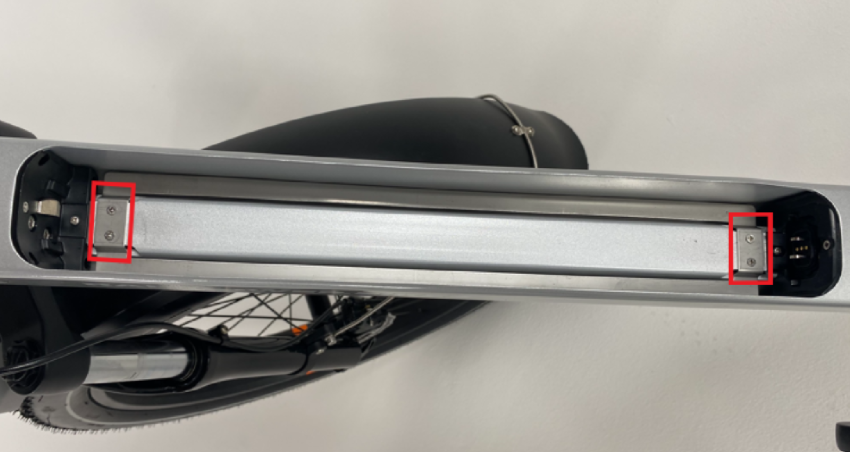
- Remove the two bolts on the battery mount using a Phillips head screwdriver, and set them aside.
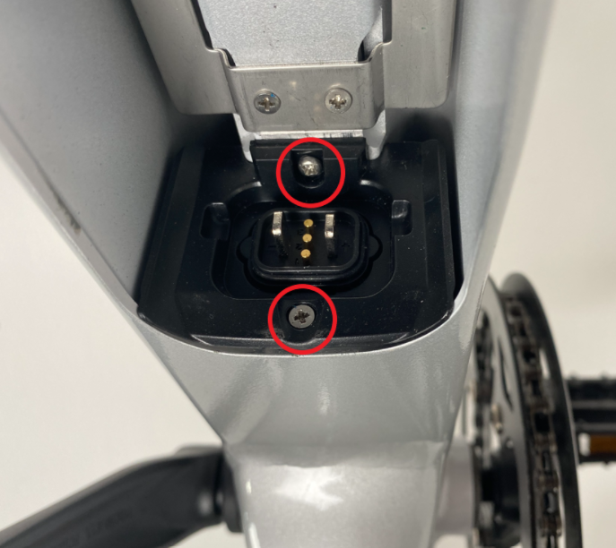
NOTICE: The bolt furthest back has a round head and the other is a flat head. Make sure that the flat head bolt goes back in the correct place when reinstalling the battery mount. - Remove the battery mount and locate the battery connector. Unplug it by pulling both ends apart without twisting, inspect the inside, and if it looks normal, carefully reconnect it.
- Reinstall the battery mount. Push the connectors back into the slot and, using the Phillips head screwdriver, thread in the round bolt partially. Then move on to the flat head bolt and tighten both.
TIP: If the bolt slips, you may need to tilt the bike so that the bolt falls out of the battery slot. There is a hole at the bottom of the downtube. - Reinstall the internal cable cover. Using the Phillips head screwdriver, reinstall the internal cable cover. Thread in all four bolts partially, and then tighten completely.
- Reinstall the battery and turn on the bike. If the error continues, turn off the bike, remove the battery, and discharge remaining power. Then begin to check the remaining connectors using the "isolation steps" outlined below.
Isolation steps
Follow the steps below to check the remaining connectors, making sure to leave the connector unplugged when turning the bike back on. (This can help isolate a part that may be causing an error.)
- Locate and unplug the connector. Snip any nearby zip ties if you need cable slack, and pull each side of the connector apart, without twisting, to unplug.
- Inspect the inside of the connector. If the inside is damaged, dirty, or wet, the part may need to be replaced. Take a photo and contact Product Support for help.
- With the connector unplugged, reinstall the battery, turn the bike on, and check whether the error is resolved.
- If the error is resolved: The part that is unplugged may have caused the error. Make note of which part it is and contact Product Support for help.
- If the error continues: Turn off the bike, remove the battery, and discharge remaining power. Then carefully reconnect it.
Trace the cable coming out of the left crank arm (the side without the chain). The connector's interior will be orange.
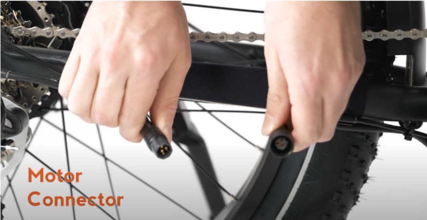
Trace the cable coming out of the motor, at the chainstay on the bike’s left side, to the connector. The connector's interior will be black.
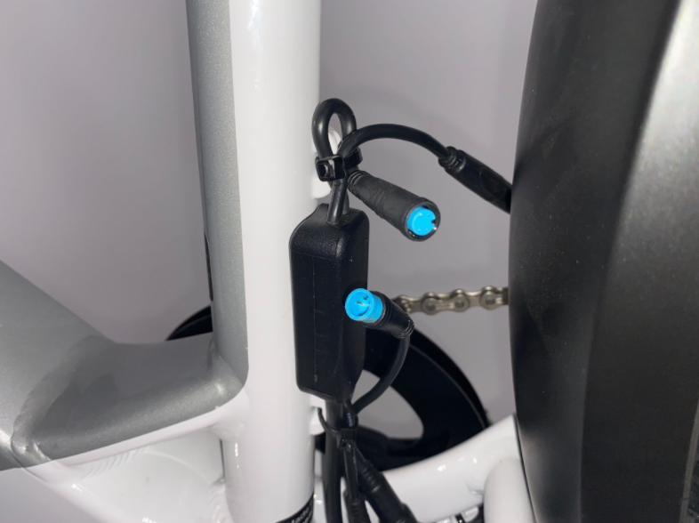
Trace the taillight cable from the junction box mounted on the seat tube to the front end of the rear fender (near the chainstay). The connector's interior is blue. The cable is routed through the rear fender and connected to the taillight. Make sure the cable is not damaged anywhere. This may require you to remove the rear wheel to inspect the cable run and connection to the taillight inside the fender.
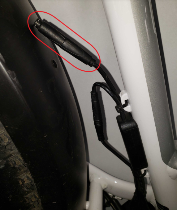
Locate the accessory connector near the bottom of the seat tube. It will have a black cap on it if it is not being utilized, and its interior is black.
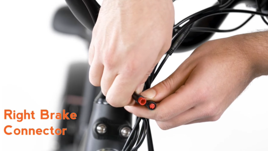
Find one of the brake connectors by tracing the cable from one brake lever on the handlebar to the connector. Its interior will be red. Perform the isolation steps on this connector, and then perform it on the brake connector that goes with the other brake lever.
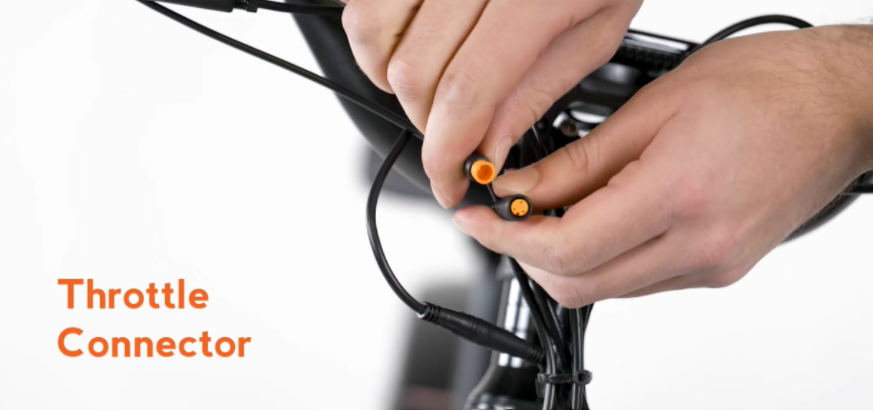
Trace the cable from the throttle on the handlebar to the connector at the front of the bike. Its interior will be orange.
How you locate your front accessory port will depend on whether you have a jumper cable or not. See the illustration below that applies to your bike. The interior of the accessory port is black.
Above: Wiring harness without a jumper cable. The accessory port is labeled "F" and has a protective cover on its end.
Above: Wiring harness with a jumper cable. The accessory port is connected to the jumper cable at the arrow labeled "I."
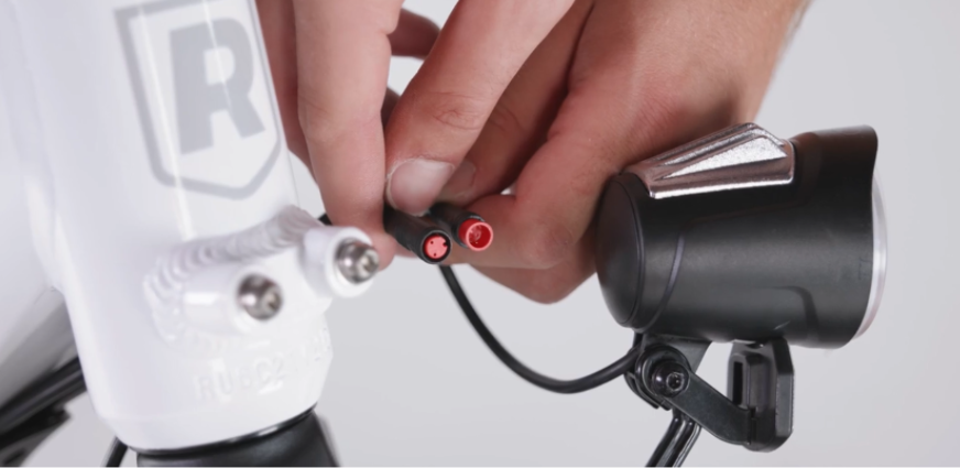
Trace the cable from the headlight to find your headlight connector. Its interior is red.
If the issue persists after completing the connector check, contact Rad Power Bikes Product Support.
If you resolve the issue, replace any snipped zip ties and trim them to be flush and smooth. Use flat-side cutters to snip off zip tie excess. Ensure the cut is flush and smooth, with no sharp point.
Check that all cables are out of the way of moving parts, and turn the handlebar to check that it can move freely.
Reinstall the battery, test the bike fully, and ride Rad!