If the LCD display shows an “Error 30” code (communication error), perform a connector check. Checking that all connectors are secure and undamaged can help diagnose electrical issues and make sure your ebike is safe and fun to ride.
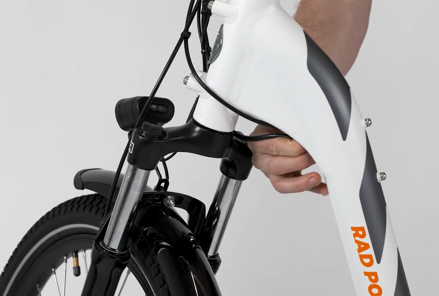
This guide uses a 2019 RadCity Step-Thru but the steps will be the same for most RadCity models.
Tools Needed:
- Flat side cutters
- Digital camera
- Flat head screwdriver
- Several replacement zip ties
The process for checking the connectors below will involve unplugging the connector, inspecting the inside for damage, plugging in the connector, and turning on the bike to check if the error persists while the connector is plugged in.
- Get the bike ready for maintenance. Turn off the bike, remove the battery, and press MODE to discharge remaining power.
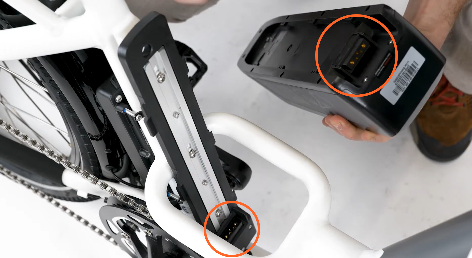
- Check the battery and battery mounting tray terminal contacts. Visually inspect the terminal contacts. If they are in good condition, reinstall the battery and turn on the bike to check if the issue is resolved. If the bike will not turn on, remove the battery, discharge remaining power, and check the next connector.
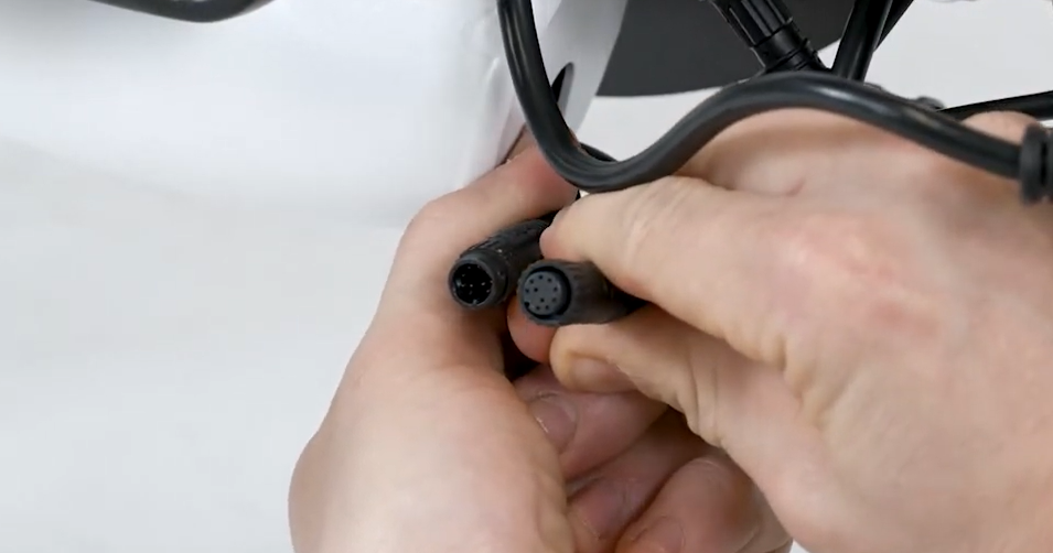
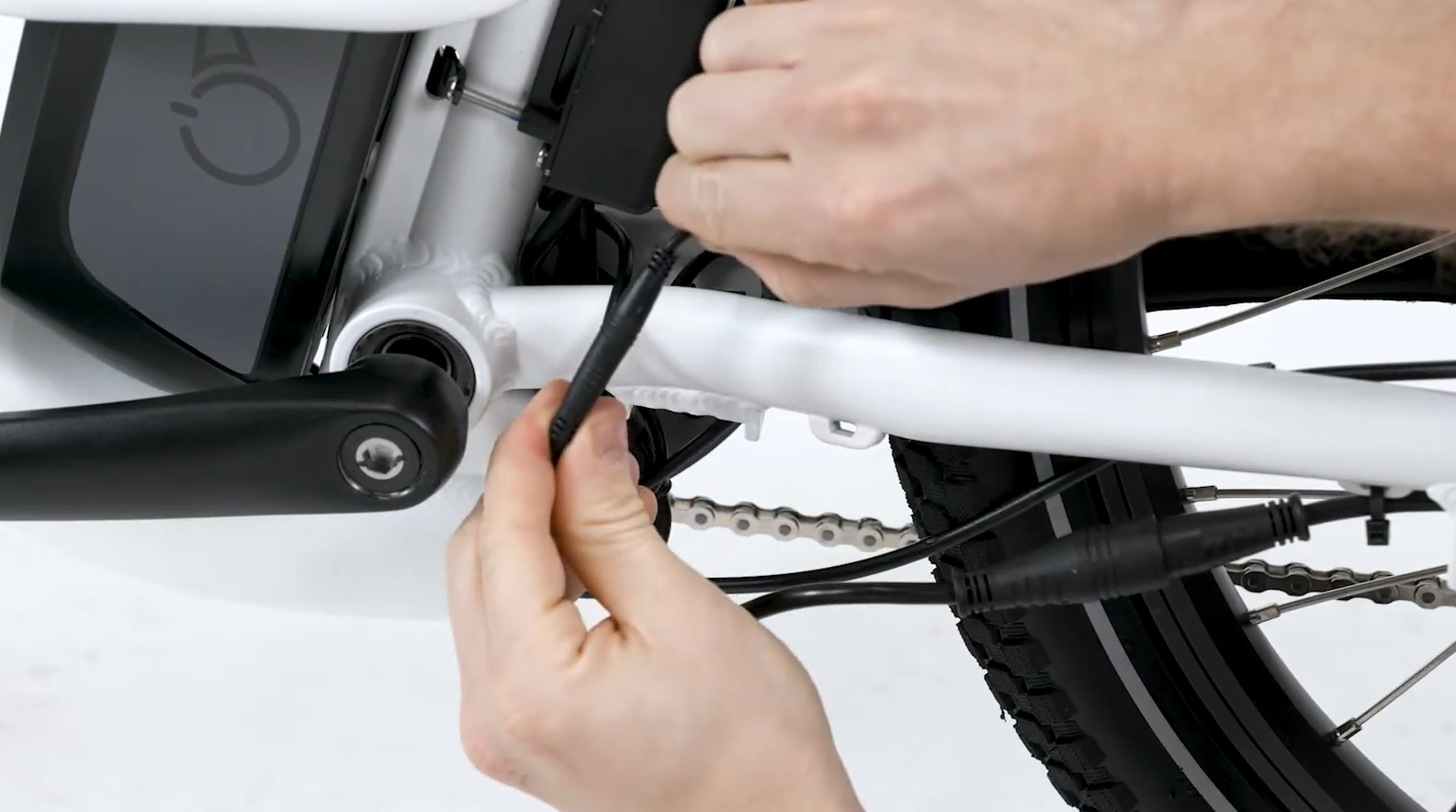
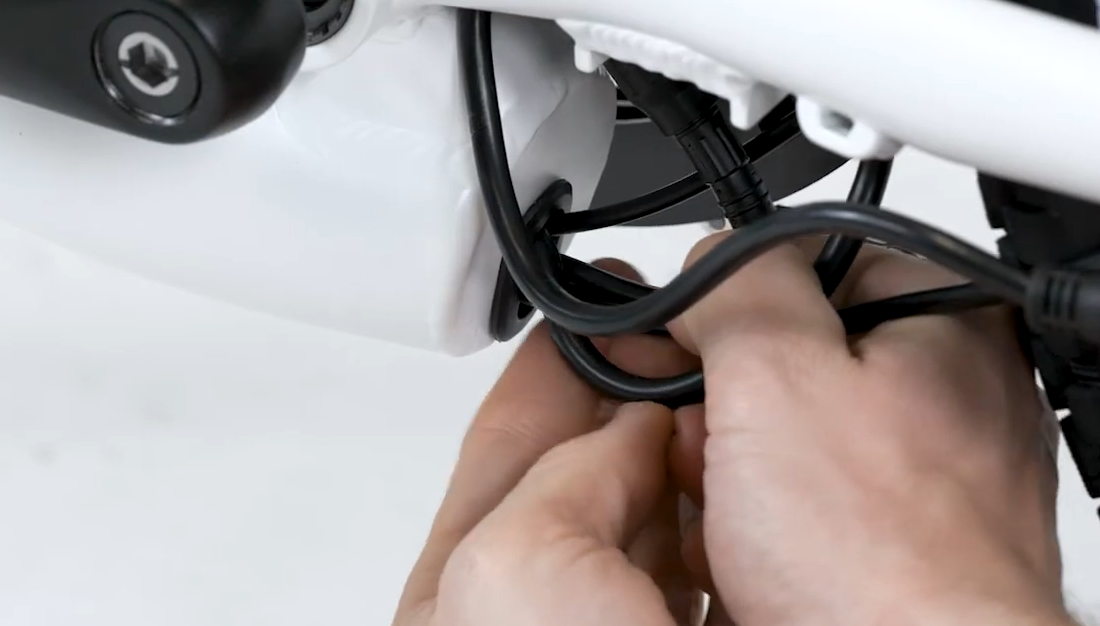
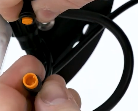
- Locate and unplug the connector, starting with the battery connector. Follow the cable from the part to the connector. Snip zip ties for easier access, then pull each side of the connector directly apart without twisting.
- Inspect the inside of the connector. If the inside of the connector is wet, dirty, or damaged, take a photo and contact Product Support. If the connector looks normal, continue to the next step.
- Plug in the connector. If the connector has no visible damage, line up the internal notch and pins (and external indicators) and press directly together without twisting.
- Check if the error persists. Reinstall the battery, turn on the bike, and check if the error persists. If the error persists, continue to the next step.
- Check the next connector. Turn off the bike, remove the battery, discharge remaining power, and check the next connector.
Repeat these steps with the three connectors listed below; the battery connector, display connector, and wiring harness connector.
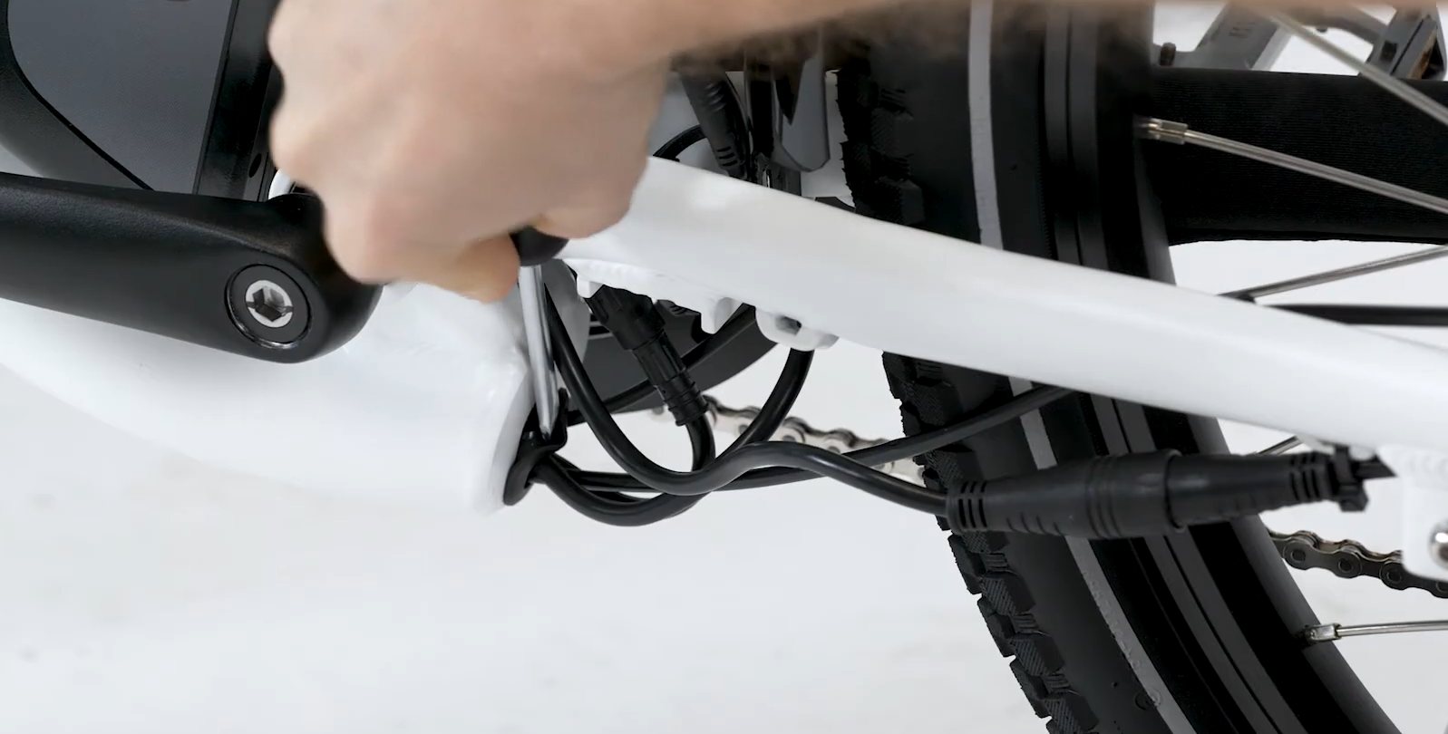
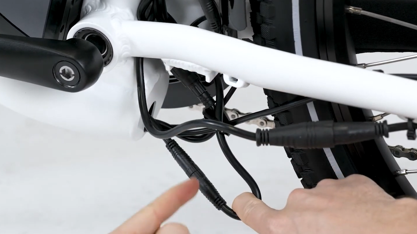
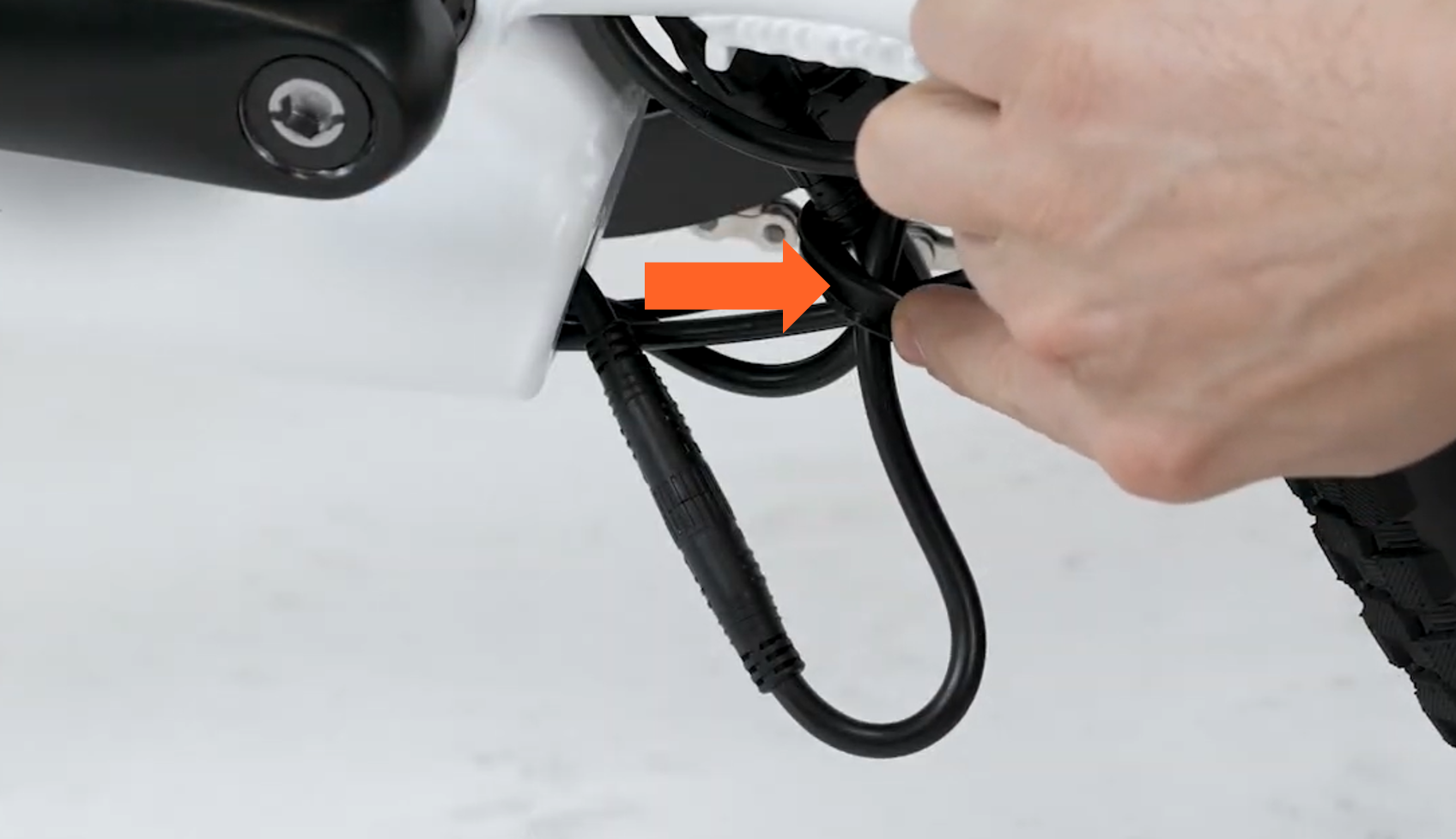
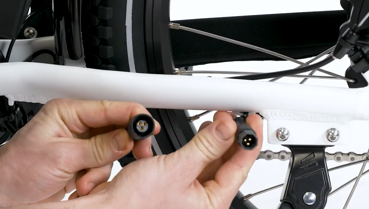
Battery Connector
Location: Near the bottom bracket
Color: Black inside
Check the connection between the battery and the controller. The battery connector is the large connector located near the bottom bracket. The connector is flat on one side and is black inside with two large prongs.
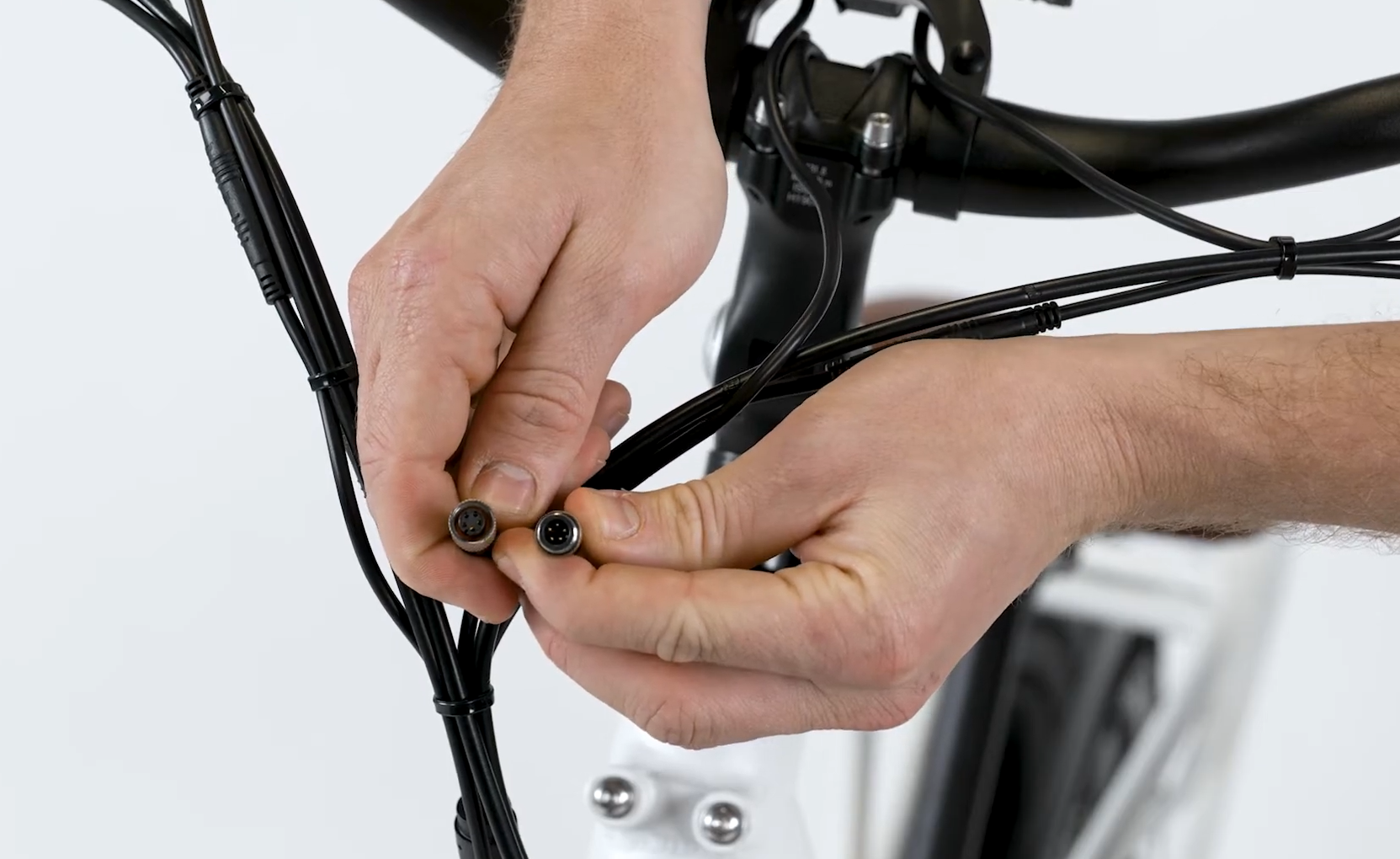
Display Connector
Location: Handlebar area
Color: Black inside
Untwist the metal portion of the connector, then pull directly apart without twisting. To reconnect, align the internal notch and pins, and twist the metal portions until the connector is secure.
Follow the steps below to check the remaining connectors.
Note: The process for checking the connectors below will involve unplugging the connector and turning on the bike to check if the error persists while the connector is still unplugged.
- Get the bike ready for maintenance. Turn off the bike, remove the battery, and press MODE to discharge remaining power.
- Locate and unplug the connector. Follow the cable from the part to the connector. Snip zip ties for easier access, then pull each side of the connector directly apart without twisting.
- Inspect the inside of the connector. If the inside of the connector is wet, dirty, or damaged, take a photo and contact Product Support. If the connector looks normal, continue to the next step.
- Check if the error persists with the connector unplugged. Leave the connector unplugged. Reinstall the battery, turn on the bike, and check if the error persists. If the error persists, continue to the next step.
If the error is resolved when the connector is unplugged, the part may need to be replaced. Contact Product Support for more help.
- Turn off the bike and plug in the connector. If the error persists, turn off the bike, remove the battery, and discharge remaining power. If the connector has no visible damage, line up the internal notch and pins (and external indicators) and press directly together without twisting.
- Repeat steps 1 through 5 on each connector listed below until the error is resolved. Once resolved, replace zip ties and trim to be flush and smooth. Test the bike fully and ride Rad!
Motor Connector
Location: Near chainstay, on the right side of the bike
Color: Black inside
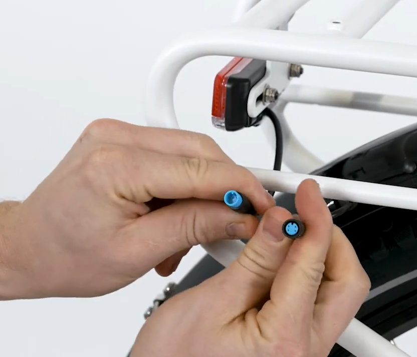
Taillight Connector
Location: Back of the bike
Color: Blue inside
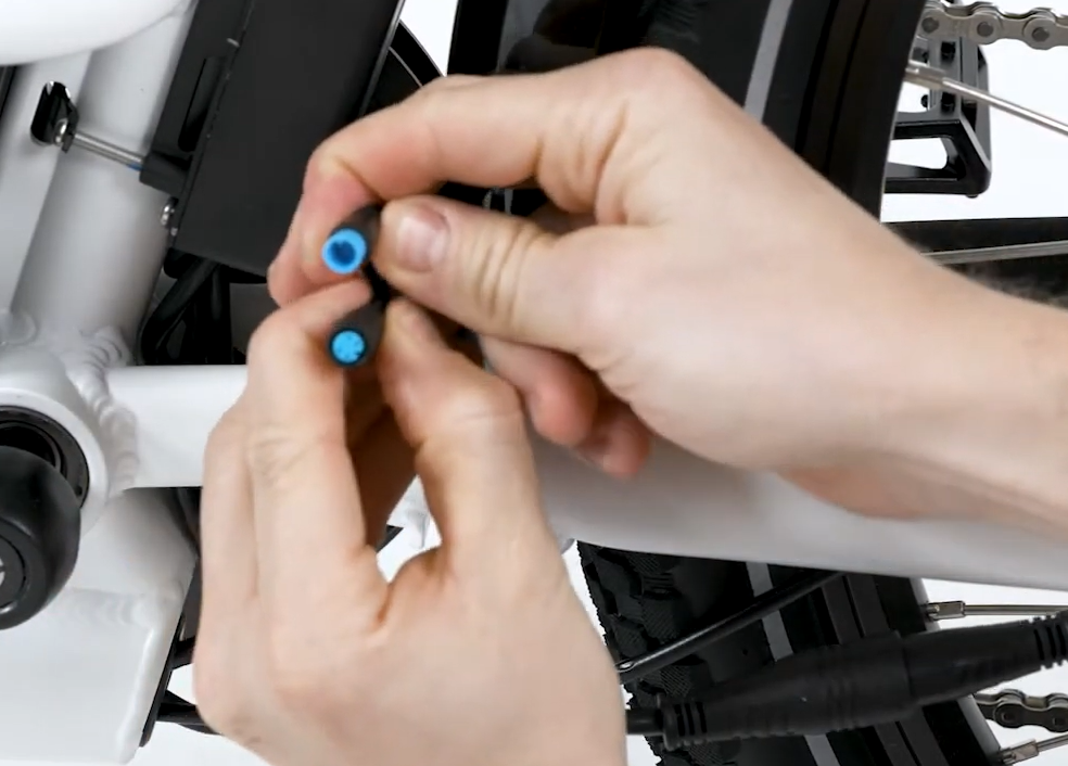
Second Taillight Connector
Location: On rear rack
Color: Blue inside
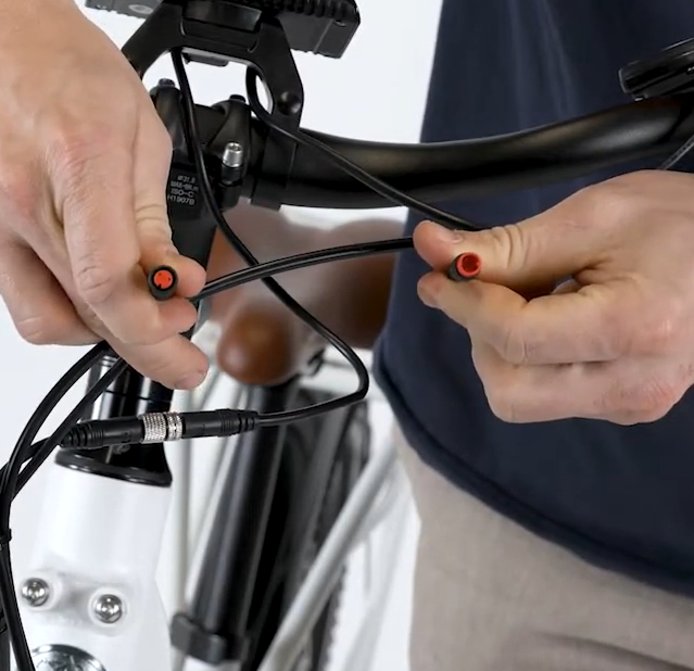
Left Brake Connector
Location: Handlebar area - left side
Color: Red inside
.PNG?revision=1)
Right Brake Connector
Location: Handlebar area - right side
Color: Red inside
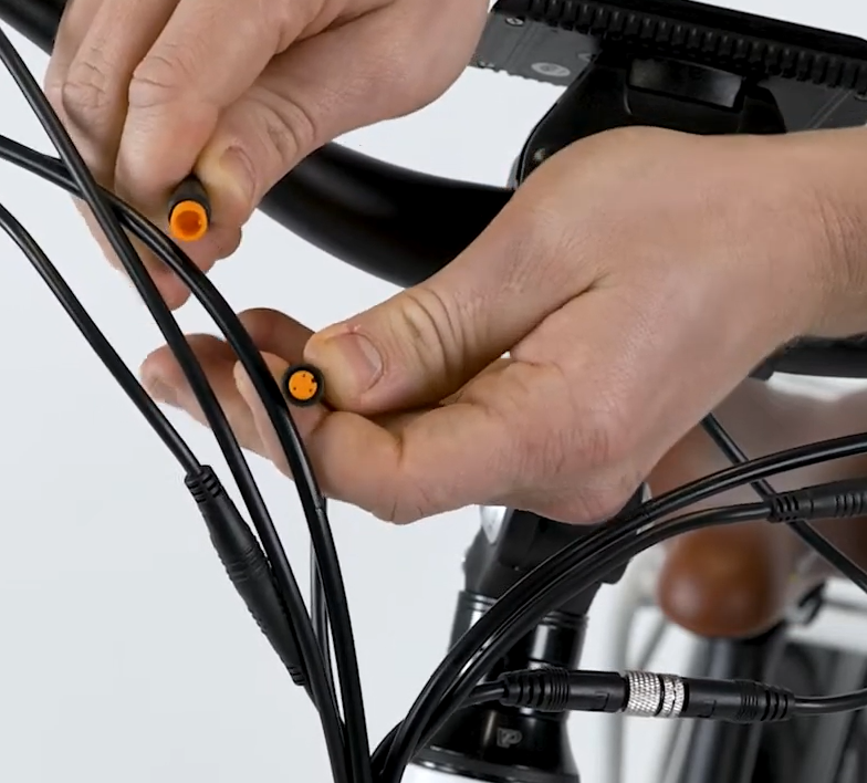
Throttle Connector
Location: Handlebar area
Color: Yellow inside
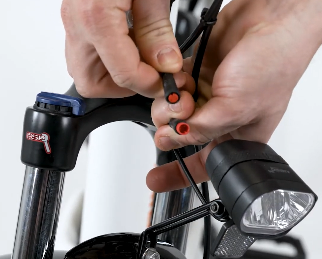
Headlight Connector
Location: Front of the bike
Color: Red inside
Pedal Assist (PAS) Sensor Connector
Location: Near seat tube
Color: Yellow inside
Once the connector check is complete, replace all zip ties and snip zip tie excess so the cut is flush and there are no sharp points that could damage cable housing.
Ensure the brake cable and motor connector are secured clear of the rear wheel and that all cables are free from any moving parts.