RadRover 5 (2020) error 30 / connector check guide
In the unlikely event you see an error 30 message on your RadRover 5, follow the steps in the video and article below to troubleshoot. The steps in this guide can also be used to troubleshoot other RadRover model years.
By first checking that all connectors are secure and in good condition, you can resolve or help identify the cause of the error message.
Tools Needed:
- Flat side cutters
- Flathead screwdriver
- A camera
- String (several inches longer than the length of the downtube)
- Electrical tape
- Zip ties
The process for checking the connectors below will involve unplugging the connector, inspecting the inside for damage, plugging in the connector, and turning on the bike to check if the error persists while the connector is plugged in.
- Get the bike ready for maintenance. Turn off the bike, remove the battery, and press MODE to discharge remaining power.
- Check the battery and battery mounting tray terminal contacts. Visually inspect the terminal contacts. If they are in good condition, reinstall the battery and turn on the bike to check if the issue is resolved. If the bike will not turn on, remove the battery, discharge remaining power, and check the next connector.
- Locate and unplug the connector, starting with the battery connector. Follow the cable from the part to the connector. Snip zip ties for easier access, then pull each side of the connector directly apart without twisting.
- Inspect the inside of the connector. If the inside of the connector is wet, dirty, or damaged, take a photo and contact Product Support. If the connector looks normal, continue to the next step.
- Plug in the connector. If the connector has no visible damage, line up the internal notch and pins (and external indicators) and press directly together without twisting.
- Check if the error persists. Reinstall the battery, turn on the bike, and check if the error persists. If the error persists, continue to the next step.
- Check the next connector. Turn off the bike, remove the battery, discharge remaining power, and check the next connector.
Repeat these steps with the three connectors listed below; the battery connector, display connector, and wiring harness connector.
Location: Near the bottom bracket
Color: Black inside
Check the connection between the battery and the controller. The battery connector is the large connector located near the bottom bracket. The connector is flat on one side and is black inside with two large prongs.
Location: Handlebar area
Color: Black inside
Untwist the metal portion of the connector, then pull directly apart without twisting. To reconnect, align the internal notch and pins, and twist the metal portions until the connector is secure.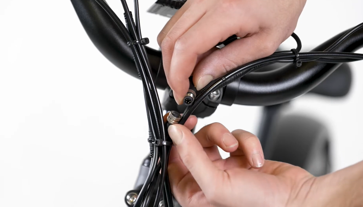
Location: At the bottom of the downtube
Color: Black inside
To access the connector:
- Turn the handlebar to the side to create cable slack, then feed the wiring harness cable into the downtube.
- Use a flat head screwdriver to carefully unseat the rubber grommet at the bottom of the downtube.
- Unplug, inspect, and reconnect the wiring harness connector. Gently pull the connector out of the downtube and check the connector.
- Insert the connector into the downtube. Carefully push the connector back into the downtube, reinstall the grommet, and check if the issue is resolved.
.gif?revision=1)
If the connector disconnects inside of the downtube:
- Remove the grommet on the upper cable opening and pull the wiring harness out of the downtube fully. Pull the cable and top half of the connector out of the cable opening in the frame.
- Tie the string to the top half of the connector end and tape it to keep it secure.
- Insert the string and connector end into the upper cable opening. Use the cable to help move the string through the downtube and out of the lower cable opening.
- Pull the string at the bottom of the downtube to pass the connector end through the downtube, out of the lower cable opening, and access the connector.
- Remove the tape, untie the string, and check the connector.
Follow the steps below to check the remaining connectors.
Note: The process for checking the connectors below will involve unplugging the connector and turning on the bike to check if the error persists while the connector is still unplugged.
- Get the bike ready for maintenance. Turn off the bike, remove the battery, and press MODE to discharge remaining power.
- Locate and unplug the connector. Follow the cable from the part to the connector. Snip zip ties for easier access, then pull each side of the connector directly apart without twisting.
.PNG?revision=1)
- Inspect the inside of the connector. If the inside of the connector is wet, dirty, or damaged, take a photo and contact Product Support. If the connector looks normal, continue to the next step.
- Check if the error persists with the connector unplugged. Leave the connector unplugged. Reinstall the battery, turn on the bike, and check if the error persists. If the error persists, continue to the next step.
If the error is resolved when the connector is unplugged, the part may need to be replaced. Contact us for more help. - Turn off the bike and plug in the connector. If the error persists, turn off the bike, remove the battery, and discharge remaining power. If the connector has no visible damage, line up the internal notch and pins (and external indicators) and press directly together without twisting.
- Repeat steps 1 through 5 on each connector listed below until the error is resolved. Once resolved, replace zip ties and trim to be flush and smooth. Test the bike fully and ride Rad!
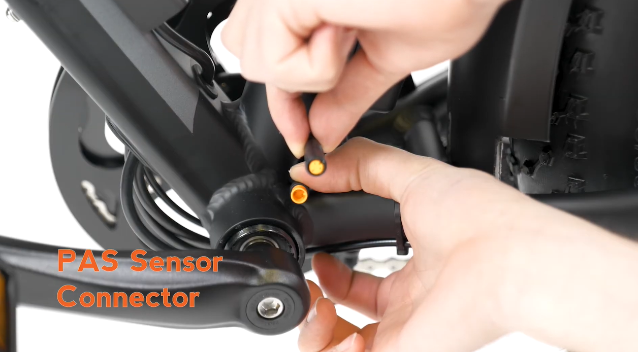
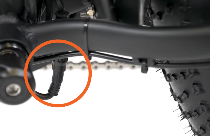
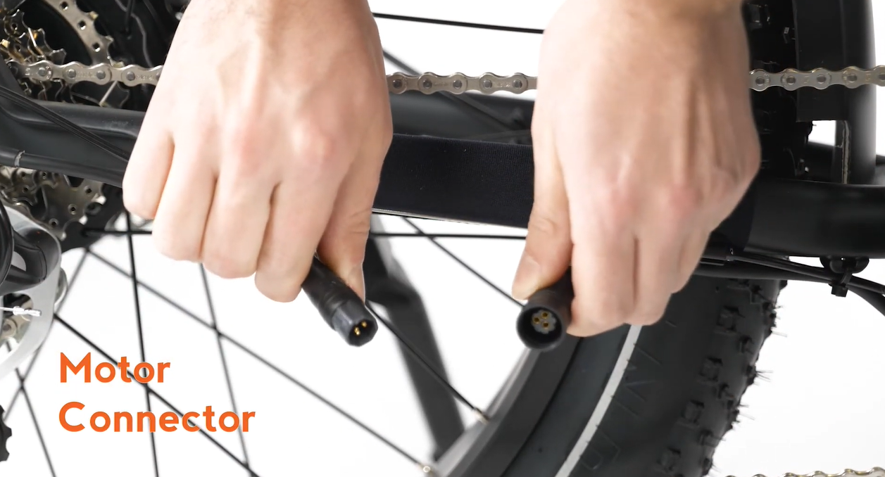
Location: Near chainstay, on the right side of the bike
Color: Black inside
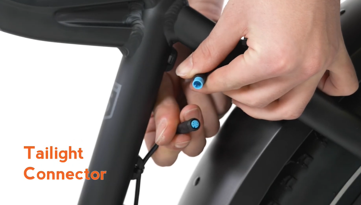
Location: Back of the bike
Color: Blue inside
Location: On rear rack
Color: Blue inside
This connector only exists on bikes that have a rear rack installed. Trace the cable from the first taillight connector to the connector plugged into the controller.
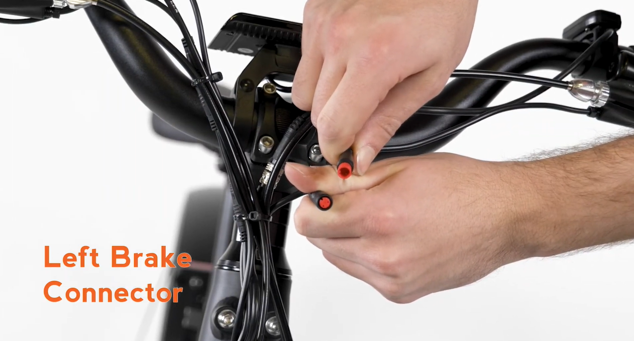
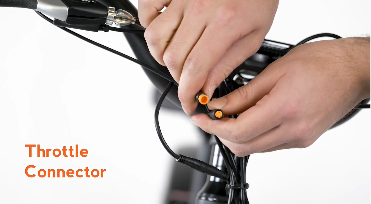
Location: Handlebar area - left side
Color: Red inside
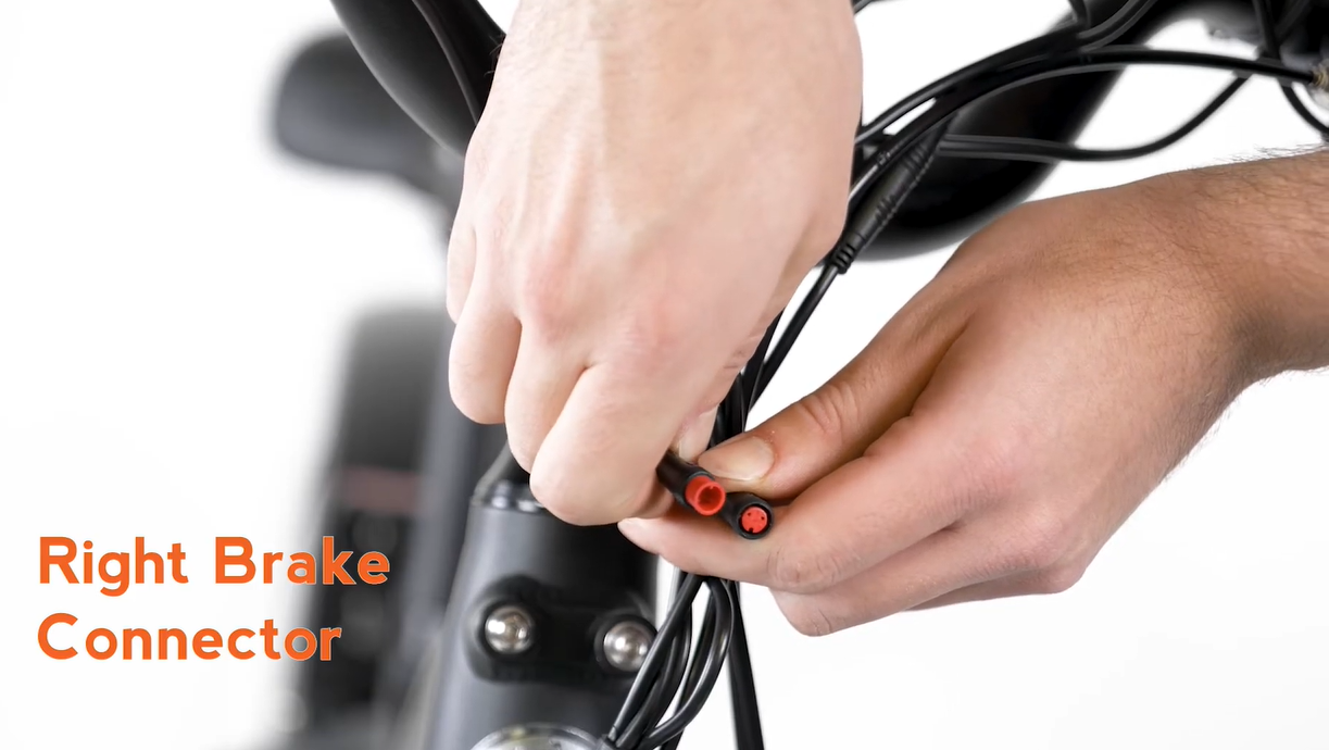
Location: Handlebar area - right side
Color: Red inside
Location: Handlebar area
Color: Yellow inside
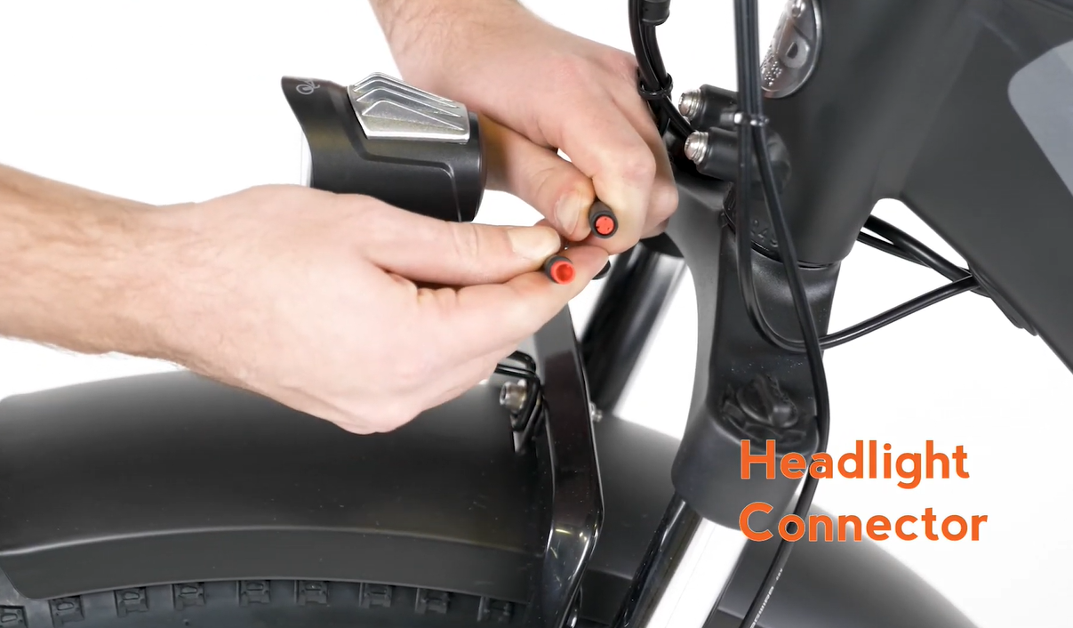
Location: Front of the bike
Color: Red inside
Location: Near seat tube
Color: Yellow inside