Integrated pedal assist (PAS) sensor replacement guide
The pedal assist sensor is designed to be replaced in the unlikely event it is damaged or determined to be non-functional by Rad Power Bikes Product Support. The video and instructions below will show you (or your bike mechanic) how to replace the sensor on bikes with the integrated PAS (all RadRunner models, RadMission, RadTrike, RadExpand 5, RadCity 5 and RadRover 6). For instructions on how to replace the external pedal assist sensor found on other models, click HERE.
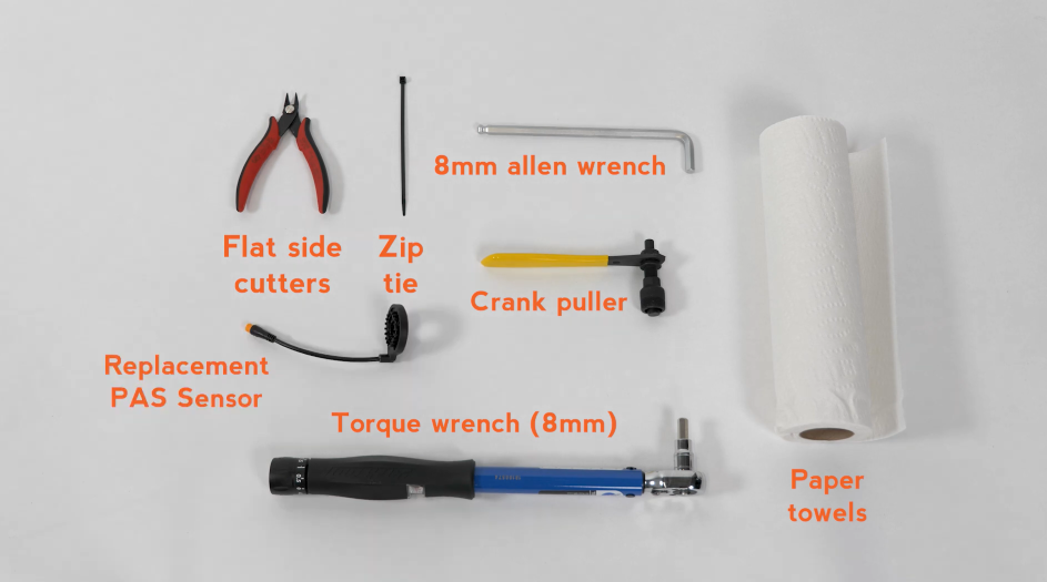
You will need:
- Flat side cutters
- 8 mm Allen wrench
- Paper towels
- Crank puller for a square taper bottom bracket spindle
- Torque wrench capable of 35 Nm with an 8 mm Allen bit
- One replacement zip tie
- The replacement PAS sensor from Rad Power Bikes.
- Prepare the bike for maintenance. Press and release the power button and use the battery key to turn the battery key barrel to the “off, unlocked” position. Remove the key, then remove the battery. Press and release the power button to discharge residual power.
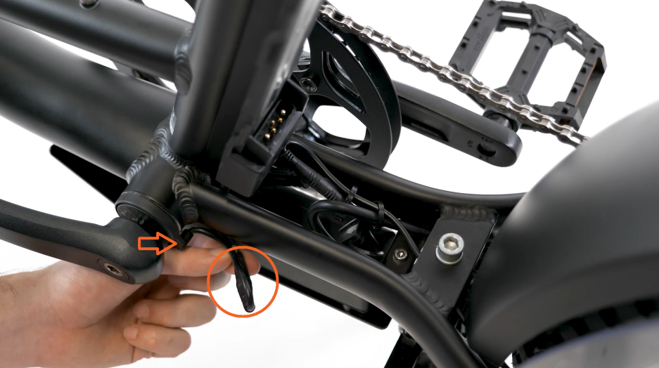
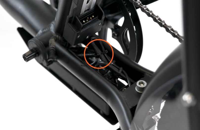
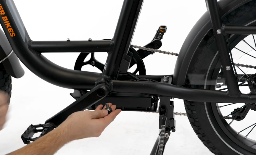
- Disconnect the PAS sensor connector. Trace the cable coming out of the PAS sensor (between the left crank and bottom bracket) to the connector below the battery mounting tray. Use flat side cutters to snip zip ties if needed. Pull directly apart without twisting to unplug.
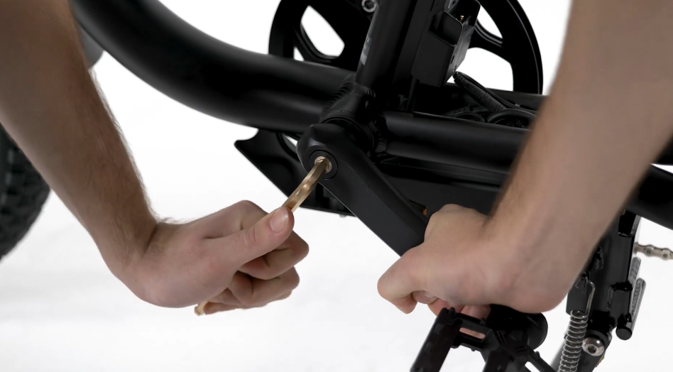
- Remove the crank on the left side of the bike:
- Use an 8 mm Allen wrench on the crank bolt head and turn counterclockwise to loosen and remove the crank bolt.
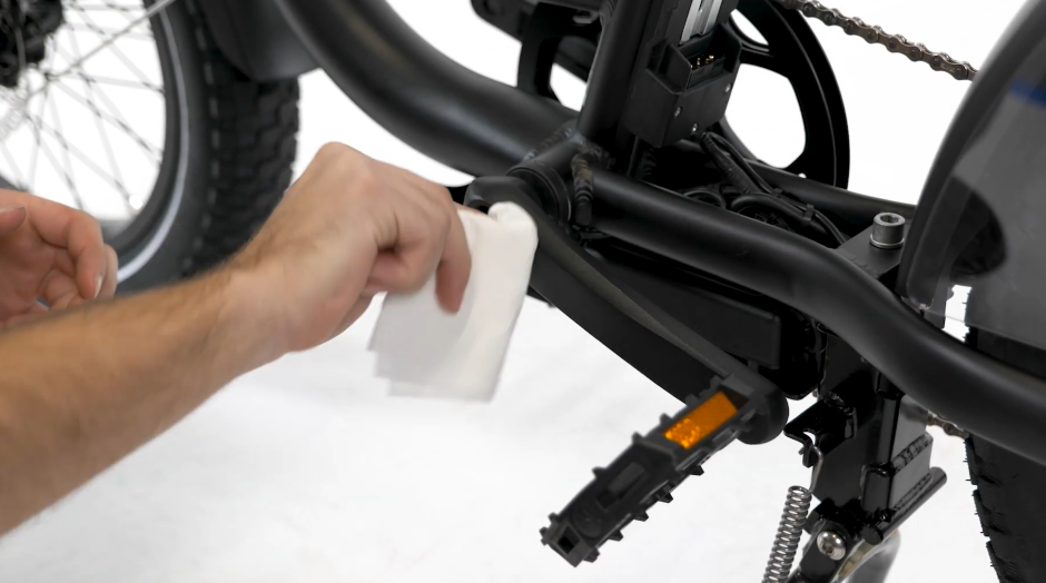
- Clean the crank arm threads. Inspect the threads of the crank arm bolt hole and use a clean paper towel to remove any grit, which can damage the threads.
- Prepare the crank puller tool. Ensure the inner bolt (the press-portion) is at least flush with, or slightly below, the edge of the outer (threaded) portion of the tool. This will ensure the tool threads can fully engage the threads on the crank (without being prevented from threading fully by the inner bolt).
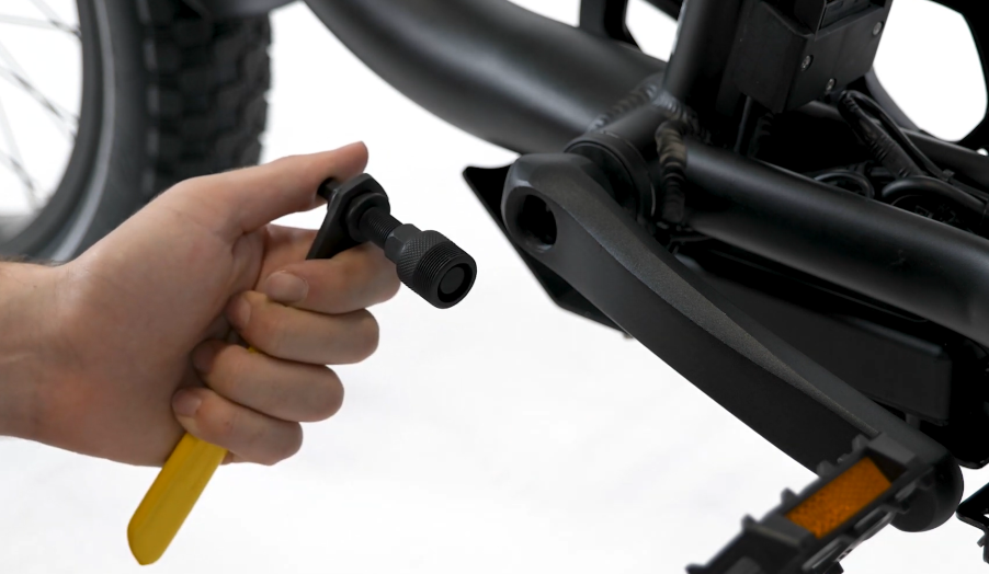
- Carefully thread the outer portion of the crank puller tool into the crank arm bolt hole by hand (about five full turns). Use caution to not cross thread or damage the threads. The outer portion of the crank puller tool will thread easily when properly aligned.
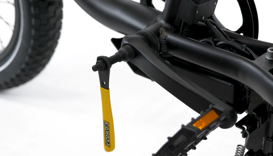
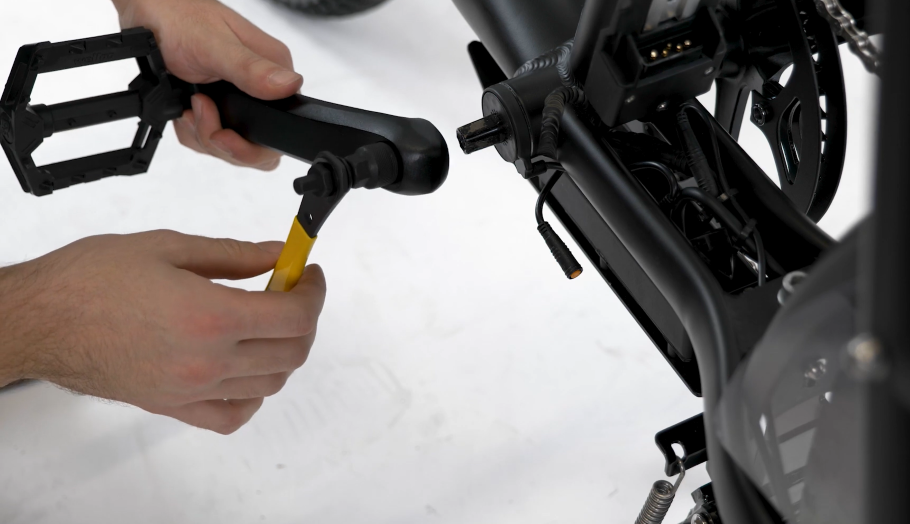
Secure the crank puller tool’s outer portion fully before engaging the inner bolt. This will ensure the crank and tool threads have as much gripping power as possible and avoid causing irreversible damage to the crank. - Press the crank off the bottom bracket spindle with the inner bolt of the crank puller tool. Turn and then leverage the handle on the tool so the inner bolt pushes against the bottom bracket to unseat the crank. Carefully remove the crank puller tool from the crank.
- Use an 8 mm Allen wrench on the crank bolt head and turn counterclockwise to loosen and remove the crank bolt.
Use caution and keep fingers clear of the space between the crank and the tool handle to avoid injury. The crank can suddenly release from the bottom bracket.
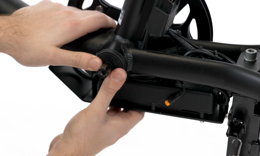
- Remove the PAS sensor. Note the orientation of the PAS sensor and pull it directly off the bottom bracket spindle.
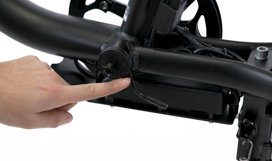
- Slide the new PAS sensor onto the bottom bracket spindle. Align the splines so the PAS sensor sits flush with the edge of the bottom bracket.
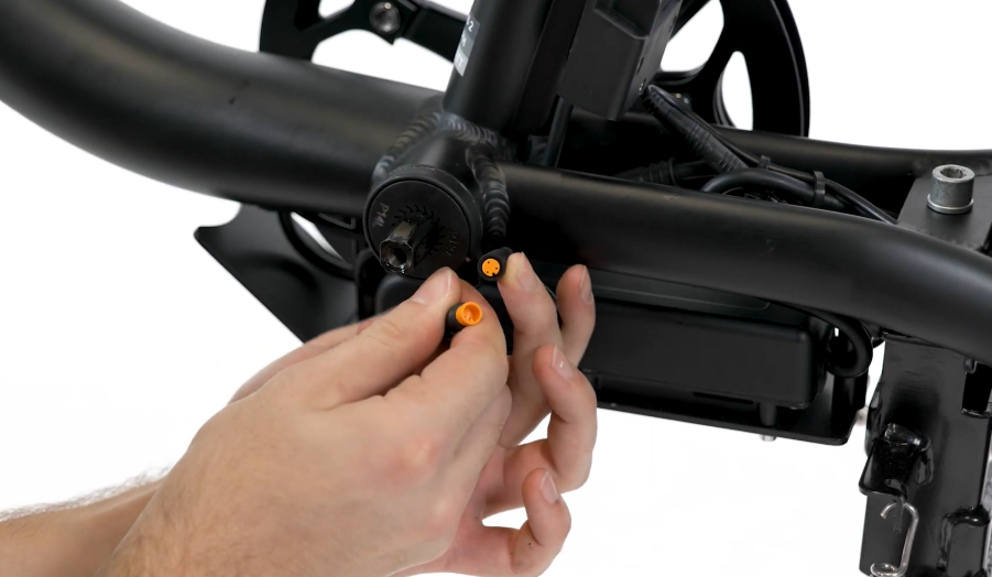
- Connect the PAS sensor. Plug in the PAS sensor by aligning the internal notch and pins (and external arrows) on the connector, and press directly together without twisting to seat the connection.
- Push the connector between the controller and the chainstay.
- Secure the PAS sensor cable with a zip tie so it is away from any moving parts. Use flat side cutters to snip zip tie excess and ensure the cut is flush so there are no points that could damage cable housing.
- Reinstall the crank on the left side of the bike:
- Align the crank so the two cranks form a line, with the pedals on either end.
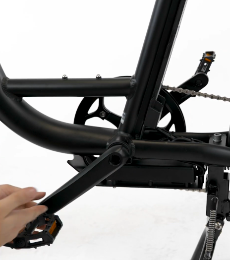
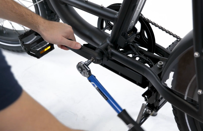
- Reinstall the left crank bolt using an 8 mm Allen wrench, tightening clockwise.
- Torque the bolt to 35 Nm using a torque wrench with an 8 mm Allen bit.
- Align the crank so the two cranks form a line, with the pedals on either end.
It is critical to properly install and tighten the crank arm bolt to the required torque value of 35 Nm. This will help ensure the bike is safe to ride and to extend the lifespan of components. Improper tightening of the cranks (to below or above 35 Nm) can lead to dangerous situations, damage to the bike and property, serious injury, or death.
- Reinstall the battery, test the bike fully, and have your work inspected by a local, certified, and reputable bike mechanic.
If the issue persists after the wiring harness is replaced, contact Rad Power Bikes Product Support.